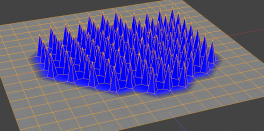
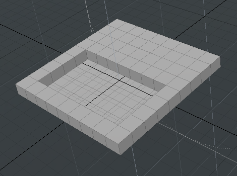
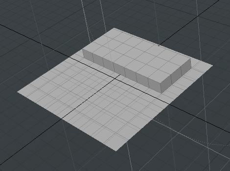
Selection Operations
The following selection types are available in the Mesh Operations list.
Convert
This selection operation converts a component selection from the given type to another component type, polygon, edge, or vertex, which is used by a procedural mesh operator in down stream in the Mesh Operations list (stack). The original source selection is retained and new selections are added.
Example
| 1. | Add a Sphere to your scene. |
| 2. | Under the layout menu, click Polygons, and select four polygons on the Sphere. |
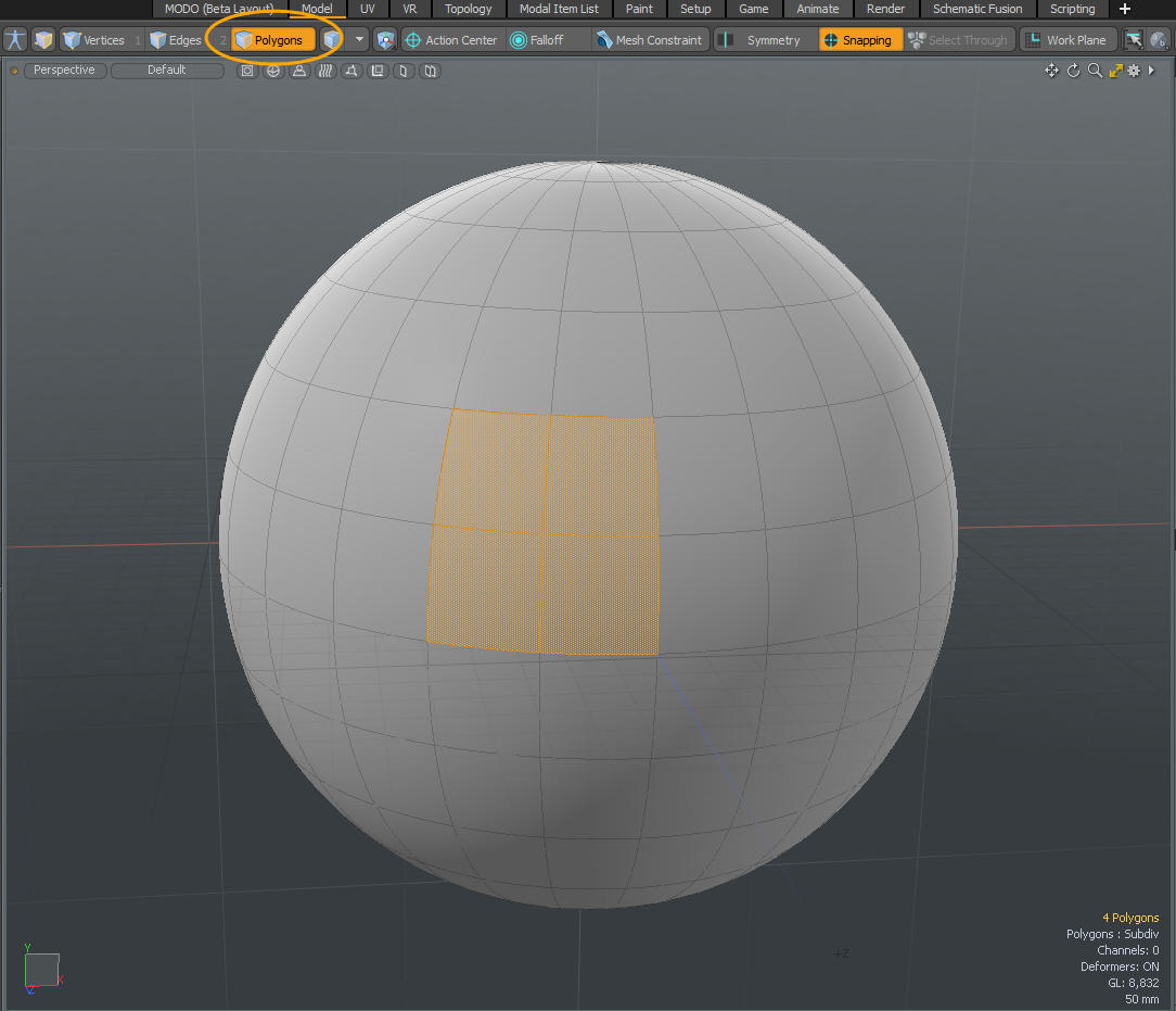
| 3. | On the top left of the menu, beside the Work Plane button, click the |
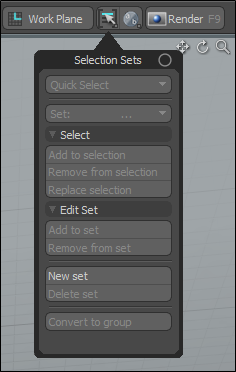
| 4. | Name this selection set Polys and click OK. |
| 5. | On the right panel, open the Mesh Ops tab, click Add Operator, and double-click Mesh Operations > Edge > Edge Bevel. |
| 6. | Drag the handles to apply a bevel on the edges. |
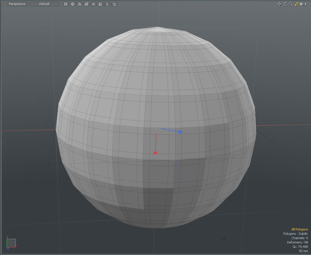
| 7. | On the Mesh Ops tab, expand Edge Bevel > Selection, and click (Add Selection). |
| 8. | Double-click Mesh Operations > Selection > Select By Selection Set. |
The beveled edges are no longer displayed because the Select By Selection Set uses a polygon selection but the Edge Bevel needs an edge selection to work.
| 9. | In the Name field, enter Polys. |
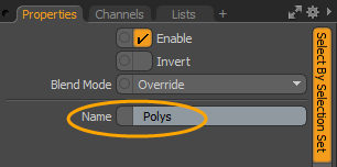
| 10. | Under Edge Bevel > Selection, click (Add Selection). |
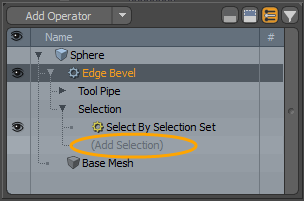
| 11. | Double-click Mesh Operation > Selection > Convert and ensure the Convert From option is set to Polygon. |
The Edge Bevel is now applied to only the Polys selection set.
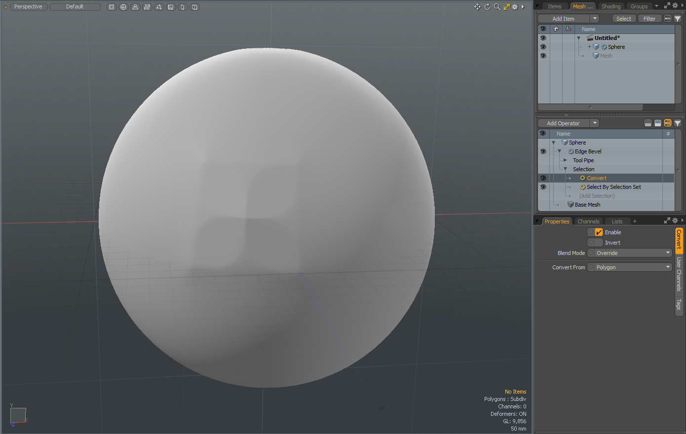
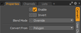
Convert Properties
|
Enable |
Enables or disables the Select by Previous Operation function. |
|
Invert |
Inverts a single selection operation or all selected operations in the Mesh Operations list. |
|
Blend Mode |
Specifies the type of blend to apply. • Override - The default behavior. The current selection overrides all selection operations below it in the Mesh Operations list. Previous selections are discarded and the new selection is used instead. • Add - Adds a new selection to the previous selection. Elements are treated as de-selected if they are de-selected by all selection operations in the Mesh Operations list. • Subtract - Removes any elements that are selected by the selection operation from the previous selection. • Multiply - Only selects elements from the new selection operation that are also selected by the first, filtering the previous selection. |
|
Convert From |
Specifies the component selection mode: Polygons, Edges, or Vertices. |
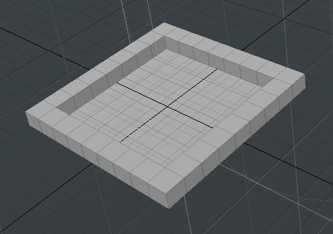
Select by Border
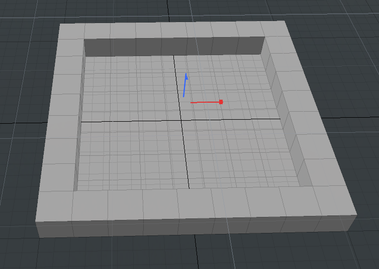
This selection operation marks elements around the boundary of a geometry for edits.
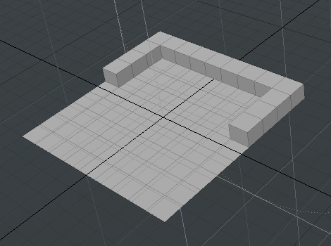
The image below shows a Polygon Bevel operation applied only to the border polygons of a plane, using the Select By Border selection operation:
Select by Falloff
When using this selection operation, selection is defined by a falloff item, which you can also add through the Mesh Operations list. The added falloff item defines which parts of the mesh get selected. You can edit the properties of the falloff item to modify the selection.
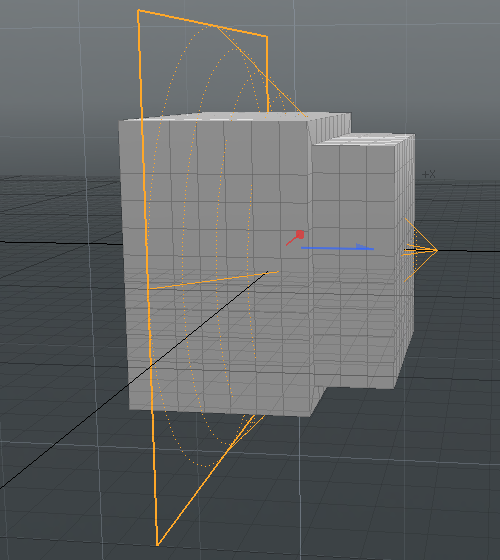
The falloff is evaluated to calculate a weight for each element, based on its world space position. If the weight is above a certain threshold, the corresponding element gets selected. The image below shows the Polygon Bevel operation applied to a region of a cube affected by Linear Falloff:
To specify a falloff:
| 1. | After adding the Select By Falloff operation, expand it in the Mesh Operations list to reveal its Falloff input. |
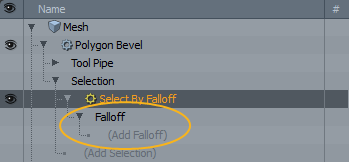
| 2. | Click (Add Falloff) to specify a falloff type for the selection operation. |
| 3. | In the Preset Browser, under New, double-click a falloff type. |
The falloff appears in the list, and you can customize it in its Properties panel below the Mesh Operations list.
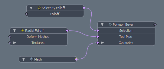
In the Schematic view, the selection operation item has a single graph input, allowing falloff items to be connected:
Select by Falloff Properties
The following options are available for this selection operation:
• Threshold - Determines whether a specific weight is treated as selected or not. Weights above the specified threshold get selected. For example, if the threshold is 50%, and the evaluated weight for an element is 40%, the element doesn't get selected. However, if the evaluated weight is 60%, it is selected.
Select by Index
This selection node allows you to define a selection using the element index in a list of indices. Each mesh element is given an index between zero and the total number of elements in the mesh. If a matching number is found in the index list, the element is selected. The list of indices are automatically populated with the current element selection when the selection operation is created.
Note: As the input mesh changes, the index mapping may change, and the selected elements may be exchanged for other elements.
To define a selection using this operation, select elements of a mesh directly in the 3D viewport, and then add a compatible mesh operation. For example, select some polygons on a mesh, then add a Polygon Bevel tool in the Mesh Operations list. The Select By Index operation is automatically added to the operation's Selection input. The mesh operation then uses the selection you defined in the 3D viewport.
Select by Index Properties
You can modify or clear your selection by clicking the Select By Index node in the Mesh Operations list. This opens the operation's properties in the Properties panel. Here you have the following options:
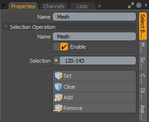
• Selection - Allows ranges of elements to be defined. For example, if the range is 0-9, the first ten elements are selected. If the range is 0,1,2, the first three elements get selected. You can also combine selection, for example, you can enter 0-9,12,14,16,18-30.
• Set - Clears the existing selection and uses the newly-selected polygons instead.
• Clear - Removes all selections.
• Add - Adds the newly-selected elements to the existing selection.
• Remove - Removes the newly-added selection.
Select By Polygon Tag
The Mesh Operation, Select By Polygon Tag, allows you to procedurally select polygons using a polygon tag to quickly locate any polygons that have a matching value. This is useful when you want to apply procedural operations to your polygon selection sets. For example, if you have modeled a table and you want to assign different colors to the legs and to the table top. The Select by Polygon Tag mesh operation allows you to quickly do that. You can specify your selection operation to be a Material, Part, or Selection Set. You can also enter any four characters in the Value field to select by arbitrary polygon tag type previously set up.
For more information about how to set up Material, Part, or Selection Set options, see Defining Shaders and Using Selection Sets.
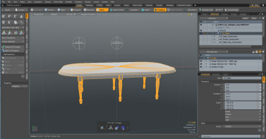
In the following example, we have previously modeled a table. This model has one mesh item and is procedural generated with Using Selection Sets created for the top and legs of the table.
To apply the Select by Polygon Tag:
| 1. | Download our example scenes and open select_by_polygon_tag-table.lxo. Alternatively, create your own model and assign selection sets. For more information, see Assigning a Selection Set. |
| 2. | From the Mesh Ops tab, select an Assign Selection Set to apply a mesh operation. In this example, select Assign Selection Set - Table Legs. |
| 3. | Click Add Operator, expand Mesh Operations > Polygon and double-click Material Tag. |
The Material Tag Properties displays in the right panel. For more information, see Assigning Material Tags.
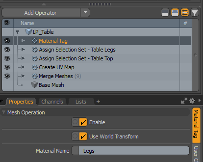
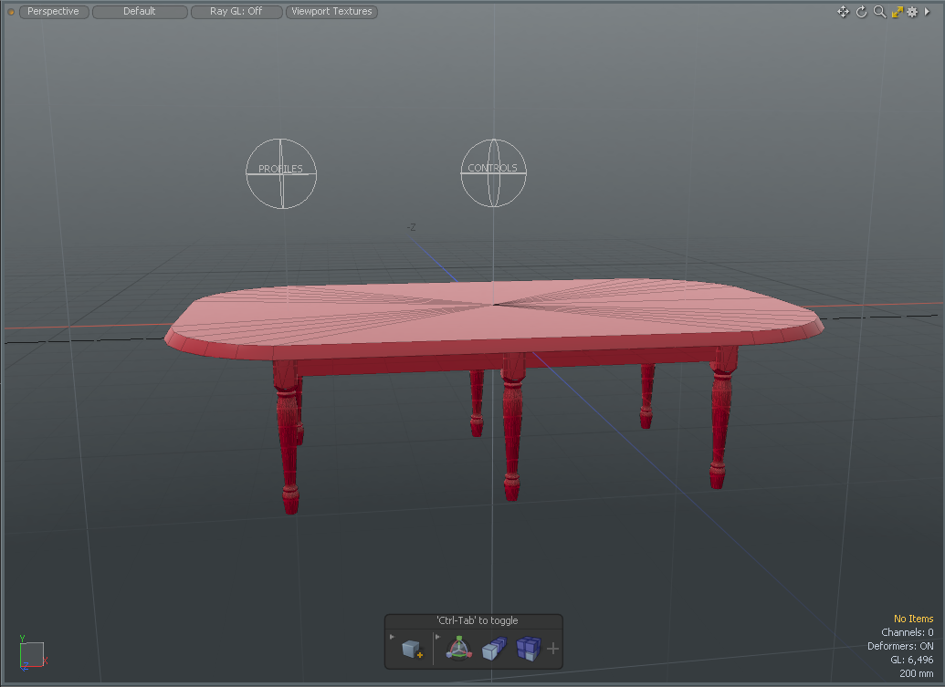
| 4. | In the Material Name field, type Legs, and then press Return. |
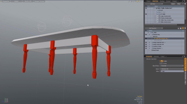
The entire table displays in red.
Note: Use the same capitalization for the created shader. To verify, open the Shading tab.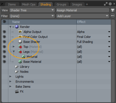
| 5. | In the Mesh Ops tab, expand Material Tag > Selection, and click Add Selection. |
The Add Operation dialog displays.
| 6. | Expand Mesh Operations > Selection and double-click Select By Polygon Tag. |
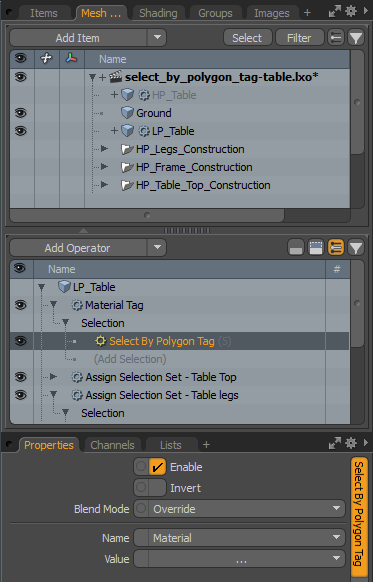
| 7. | Choose the polygon tag you want to use. In this example, select Selection Set from the Name dropdown menu. |
| 8. | Select Legs from the Value dropdown menu. |
Tip: Alternatively, you can type in the Value field. This can be four characters used by the name of the polygon tag. For example, if you had four selection sets that started with the word Leg, all polygons from all four selection sets are selected in your scene. Once done, a material is assigned to all four legs.
| 9. | Click Return to view an update in the 3D viewport. Alternatively, click in the 3D viewport and press the space bar to drop your selection. |
| 10. | From the Mesh Ops tab, select an Assign Selection Set to apply a mesh operation. In this example, select Assign Selection Set - Table Top. |
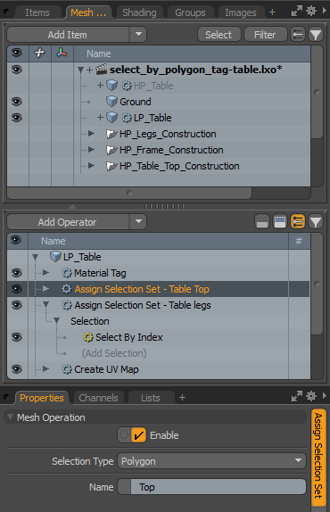
| 11. | Click Add Operator, expand Mesh Operations > Polygon, and double-click Material Tag. |
| 12. | In the Material Name field, type Top. |
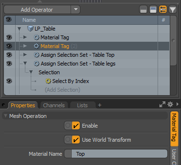
| 13. | In the Mesh Ops tab, expand Material Tag(2) > Selection, and click Add Selection. |
The Add Operation dialog displays.
| 14. | Expand Mesh Operations > Selection and double-click Select By Polygon Tag. |
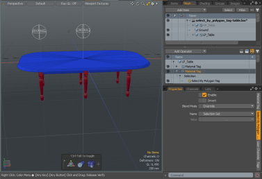
The top of the table top has a newly assigned material.
Select by Polygon Tag Properties
The following options are available for this selection node:
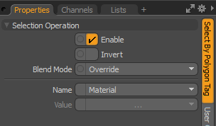
• Name - Allows you to choose the polygon tag type. The following options are available:
• Material - Uses a previously created Material Tag
Tip: A Material Tag creates a mask for the surfacing using the material and shading properties and applies them to specific surfaces. For more information, see Assigning Material Tags.
• Part - Uses a previously created Part Tag.
Tip: A Part Tag works in a similar fashion to Material Tags, offering an additional means of defining polygon groupings. For more information, see Defining Shaders.
• Selection Set - Uses a previously created component and item-based selection set. For more information, see Using Selection Sets.
• Value - Specifies which tag to match to.
Select by Pattern
The Select by Pattern selection operation creates a selection based on a pattern you define. The pattern selection specifies elements using a "True, False" pattern. Elements whose index is present in the pattern are selected. For example, the pattern "True, False" selects every other element, whereas the pattern "False, False, True" selects every third element.
On a standard grid you get the following patterns:

|

|
| True, False | False, False, True |
To use Select by Pattern:
| 1. | In the Mesh Operations list, expand the operation for which you want to define the selection, such as a Polygon Bevel. |
| 2. | Expand its Selection input and click (Add Selection). |
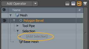
| 3. | In the Add Operator window, double-click Select by Pattern. |
The selection operation is added to the Mesh Operations list, and its properties open in the lower right panel.
| 4. | In the Properties panel, enter the required values in the Pattern field. For example, you can enter 'True, False' to select every other polygon. |
You can also enter values like '1, 0' or 'Yes, No', and Modo automatically converts them to True or False.
| 5. | Click the operation that uses the selection, and in the lower right panel, modify its Properties, as needed. |
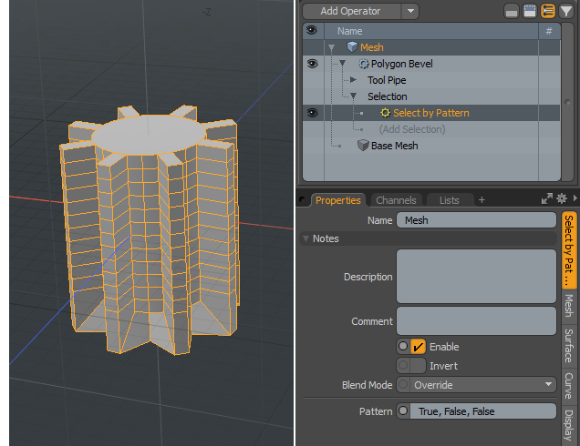
The changes are applied to the polygons according to the pattern you defined. In the example below, the Polygon Bevel operation is applied to the selection defined by the pattern 'True, False, False', which means that every third polygon is selected, starting with the first polygon in the selection.
Select by Previous Operation
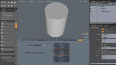
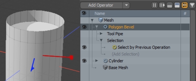
Use this selection operation to automatically leverage the results of mesh operations that are lower in a stack. For instance, if you create a cylinder using the Cylinder MeshOp you now have the beginnings of a procedural stack. Then you create a Polygon Bevel MeshOp above the Cylinder MeshOp. Since you haven’t selected anything, the bevel is applied to the entire cylinder. You could use a Select by Index Selection op to manually select exactly which polygons you want to bevel. However, since the Select by Previous Operation now supports aspects of the Cylinder MeshOp, you can now use that instead to easily and reliably select aspects of the cylinder primitive. In this case, the Caps, Top, Bottom, and Sides can be selected.
Note: Procedural operation options vary from one mesh operation to another. For example, a Bevel operation may provide separate lists for the back, side, and top polygons, whereas a Curve Fill operation may present different lists for each filled shape.
Select Elements Automatically Using Select by Previous Operation
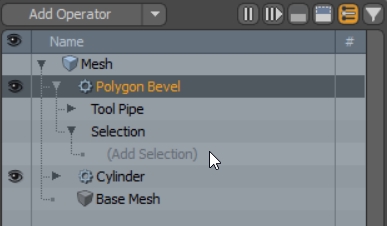
In this example, we'll create a cylinder primitive at the bottom of the stack and then we'll create a Polygon Bevel MeshOp to bevel part of the cylinder. Instead of manually selecting what to bevel, we'll use Select by Previous Operation to automatically select the Caps of the cylinder lower down in the procedural stack.
- In the Mesh Operations viewport, click Add Operator, select Create > Primitives, and then double-click Cylinder to add the mesh to the 3D viewport.
- Click Add Operator again, select Polygon, and then double-click Polygon Bevel to add the operation to the stack.
- Adjust the bevel handles in the viewport to see the result. The bevel affects the whole mesh, which results in scaling the whole cylinder.
- To automatically select the cylinder caps, drill down in the Polygon Bevel MeshOp to the Selection component.
- Click (Add Selection) and double-click Select by Previous Operation to add the selection op.
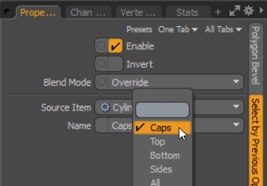
- In the Properties viewport, click the Source Item dropdown and select Cylinder.
- Click the Name dropdown to see a list of components you can select to drive operations higher up the tree. In this case, the Polygon Bevel.
- Select Caps to affect only the caps of the cylinder.
- Now, when you select the Polygon Bevel op, you can see that the bevel is only applied to the caps of the cylinder, rather than the whole mesh.
Note: Select by Previous options vary depending on the MeshOp that’s being referenced. In this example, Polygon Bevel provides separate options for the Caps, Top, Bottom, and Sides, whereas a Curve Fill operation presents different options for each filled shape.
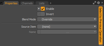
Select By Previous Operation Properties
The following options are available:
|
Option |
Description |
|
Enable |
Enables or disables the Select by Previous Operation function. |
|
Invert |
Inverts a single selection operation or all selected operations in the Mesh Operations list. |
|
Blend Mode |
Affects the blending between different layers of the same effect type. The following options are available: • Override - The default behavior. The current selection overrides all selection operations below it in the Mesh Operations list. Previous selections are discarded and the new selection is used instead. • Add - Adds a new selection to the previous selection. Elements are treated as de-selected if they are de-selected by all selection operations in the Mesh Operations list. • Subtract - Removes any elements that are selected by the selection operation from the previous selection. • Multiply - Only selects elements from the new selection operation that are also selected by the first, filtering the previous selection. |
|
Source Item |
Specifies the operation source item to apply the Select by Previous Operation to. |
|
Name |
Specifies the filter to apply to selected the operation. See the following table for Name filters available for each procedural operation. N/A denotes that there are no filters available for that operation. |
|
Procedural Operation |
Select by Previous Operation Name (where applicable) |
|
|---|---|---|
|
Select by Previous Operation can select New Edges from this operation. |
||
|
N/A |
||
|
Select by Previous Operation can select new from this operation. |
||
|
Select by Previous Operation can select new from this operation. |
||
|
N/A |
||
|
N/A |
||
|
N/A |
||
|
N/A |
||
|
Select by Previous Operation can select Caps, Cap Side A, and Cap Side B from this operation. |
||
|
Select by Previous Operation can select New Curves from this operation. |
||
|
N/A |
||
| Polygon Extrude |
N/A |
|
|
Select by Previous Operation can select Unified Polygons from this operation. |
||
|
N/A |
||
|
N/A |
||
|
N/A |
||
|
N/A |
||
|
Select by Previous Operation can select New Edges from this operation. |
||
|
Select by Previous Operation can select New Edges from this operation. |
||
|
N/A |
||
|
N/A |
||
|
All 3D Primitives |
||
|
Select by Previous Operation can select Caps, Top, Bottom, Sides, and All from all primitive operations, where appropriate. |
||
|
All 2D Primitives |
||
|
Select by Previous Operation can select Curve from all 2D primitive operations. |
||
|
All Clone Tools |
||
|
Select by Previous Operation can select all Cloned Polygons or individual Clone n from all Clone operations. |
||
Click on the following images to view an animation, which demonstrates how the Select By Previous Operation is used to query previous operations in the Mesh Operations list.
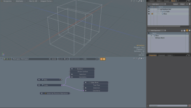
The first animation demonstrates a Cylinder in a scene and a Slice Mesh Operation with both the Split and Caps Sections options enabled. In addition, an Edge Bevel is added to the top of the Mesh Operation list. It has the Selection option set to use Select by Previous Operation with the Source Item set to Boolean and Name set to Intersecting Edges. As a result, new polygons fill the split sections.
The following animation demonstrates a Cube and a Boolean Mesh Operation with the Operation option set to Union.
In addition, an Edge Bevel Mesh Operation is added to the top of the Mesh Operation list. It has the Selection option set to use Select by Previous Operation with the Source Item set to Boolean and Name set to Intersecting Edges. As a result, the polygons that are from the surface connect to a Driver Surface.
Select Connected
With this operation, you can quickly locate connected geometry to a polygon, vertex, or edge selection. This Mesh Operation uses a previous selection method, such as Select By Index, to compute all vertices, edges, and polygons linked to the previous selection. This is useful if you have a complex model and you want to remove a selection from the parent mesh item.
The following example demonstrates applying Select Connected command to a previous selection method.
| 1. | On the top left corner of the interface, click the Preset Browser icon. |
![]()
| 2. | On the left panel of the Preset Browser, expand Cloud Assets > Meshes > Interior, and double-click Afton_Stool. |
| 3. | Under the layout menu, click Polygons. |

| 4. | Select one polygon on the seat cushion. |
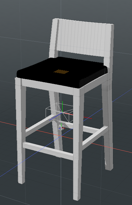
| 5. | On the right panel, click Add Operator, double-click Mesh Operations > Edit > Delete. |
The selected polygon is removed from the cushion.
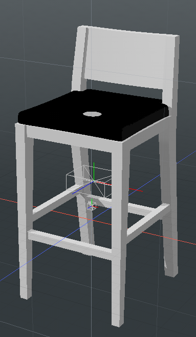
| 6. | Expand the Delete mesh operation and click (Add Selection). |
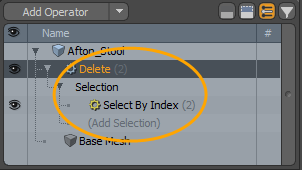
| 7. | In the Add Operations dialog, double-click Mesh Operation > Selection > Select Connected. |
All of the polygons connected to the cushion are selected and deleted.
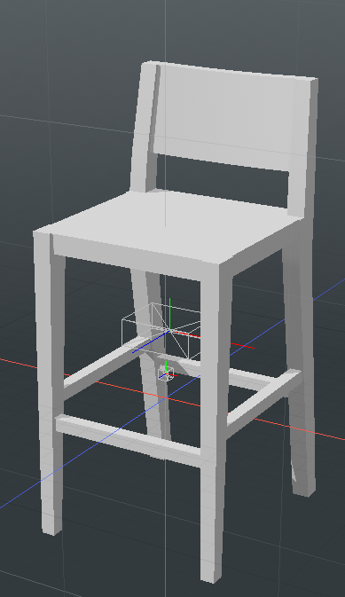
Select Coplanar Polygons
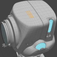
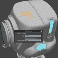
Select Coplanar Polygons is the procedural equivalent of the Coplanar Polygons Tool. It allows you to select neighboring polygons on the same plane as the original selection.
To use the operation:
| 1. | In the 3D viewport, select one or more polygons on your mesh. |
| 2. | In the Mesh Operations list, add a mesh operation that you want to apply to the selection. For instance, if you wanted to bevel the selected polygons, add the Polygon Bevel mesh operation to the list. |
Note: For more information on the Polygon Bevel mesh operation, see Procedural Polygon Bevel.
Adding the Polygon Bevel applies the operation to the selected polygon.
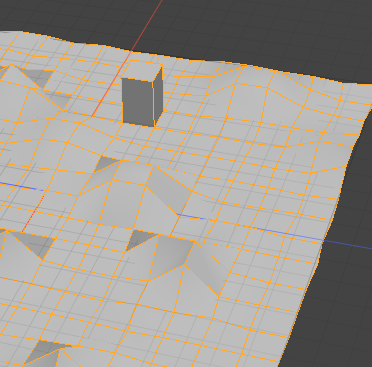
| 3. | In the Mesh Operations list, click the arrow in front of the operation's name to expand it. |
This reveals the operation's Selection input.
| 4. | Expand the Selection input by clicking the arrow in front of it. |
You can see a Select by Index already in the list. This was added when you selected the initial polygon in the 3D viewport.
| 5. | To select polygons that are coplanar with the original selection, click (Add Selection). |
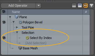
This opens the Add Operation dialog.
| 6. | Under New > Selection, double-click Select Coplanar Polygons. |
This adds the Select Coplanar Polygons mesh operation to the list, and applies the connected mesh operation to all coplanar polygons. The image below shows the selected polygons with the default settings.
Note: If no polygons are coplanar to the selection, you won't see any changes.
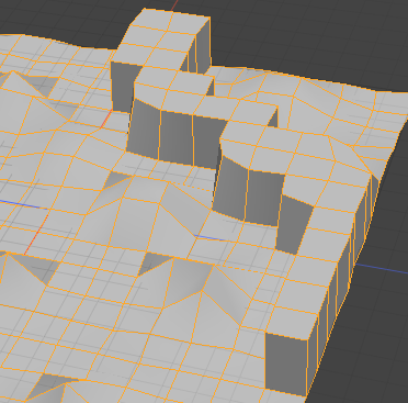
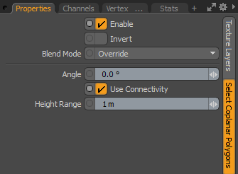
To modify the Select Coplanar Polygons mesh operation's properties, select it in the Mesh Operations list.
This displays the Properties in the lower right panel.
Select Vertex Map Value
This selection operation allows you to enter a Vertex map value and select vertices where the value is greater than or equal to the supplied value.
To use the selection operation:
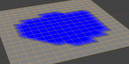
| 1. | In the Mesh Operations list, add a mesh operation that you want to apply to the selection. For instance, if you want to extrude the selected vertices, add the Vertex Extrude mesh operation to the list. In this example, we apply Vertex Extrude to the blue area. |
Note: If you're using a mesh operation that requires an edge or polygon selection, you have to add a Convert selection operation in addition to Select Vertex Map Values, to convert your vertex selection to an edge or polygon selection. For more information, see Convert.
| 2. | In the Mesh Operations list, click the arrow in front of the operation's name to expand it. |
This reveals the operation's Selection input.
| 3. | Expand the Selection input by clicking the arrow in front of it, then click (Add Selection). |
This opens the Add Operation dialog.
| 4. | Under New > Selection, double-click Select Vertex Map Value. |
This adds the Select Vertex Map Value selection operation to the list and opens its Properties on the right pane.
| 5. | In the Properties, select the relevant Map Type and Map Name, and enter the Min Value to Select. In our example, we use the Component Method, with Component set to B and the value is 2.0. Now the mesh operation only affects vertices that match the criteria. |
Select Vertex Map Value Properties
|
Enable |
Enables or disables Select Vertex Map Value. |
|
Invert |
Inverts the selection operation. |
|
Blend Mode |
Affects the blending between different layers of the same effect type. The following options are available: • Override - The default behavior. The current selection overrides all selection operations below it in the Mesh Operations list. Previous selections are discarded and the new selection is used instead. • Add - Adds a new selection to the previous selection. Elements are treated as de-selected if they are de-selected by all selection operations in the Mesh Operations list. • Subtract - Removes any elements that are specified by the selection operation from the previous selection. • Multiply - Only selects elements from the new selection operation that are also selected by the first, filtering the previous selection. |
|
Map Type |
The type of map to use the selection on. The available options are: • Weight - Stores weight strength values for falloffs and texturing. • Subdivision - A type of weight map controlling the rounding of edges on subdivision surfaces. • RGB - Defines a vertex color map based on red, green, and blue color values. • RGBA - Defines a vertex color map based on red, green, and blue color values and an additional transparency (Alpha) value. Note: For more information on Vertex Map types, see Working with Vertex Maps. |
|
Map Name |
The name of the map from which the value is read. |
|
Method |
The way the value is read: • Component - Reads the component of the map. Only applicable for RGB and RGBA maps. Weight and subdivision assume the first component. • Sum - The sum total of the components. |
|
Component |
When Method is set to Component, sets the component to select. This is only applicable to RGB and RGBA maps. |
|
Min Value to Select |
If the value is equal to or greater than this value, then the element is selected. |
Select by Range
With this operation, you can define a selection using a range of indices matching the current element index. Each mesh element is given an index between zero and the total number of elements in the mesh. If the element index falls within the range defined by the selection operation, then the element is selected. You can also set up your selection to select, for example, every second or every third element in the range.
Note: As the input mesh changes, the index mapping may change, and the selected elements may be different.
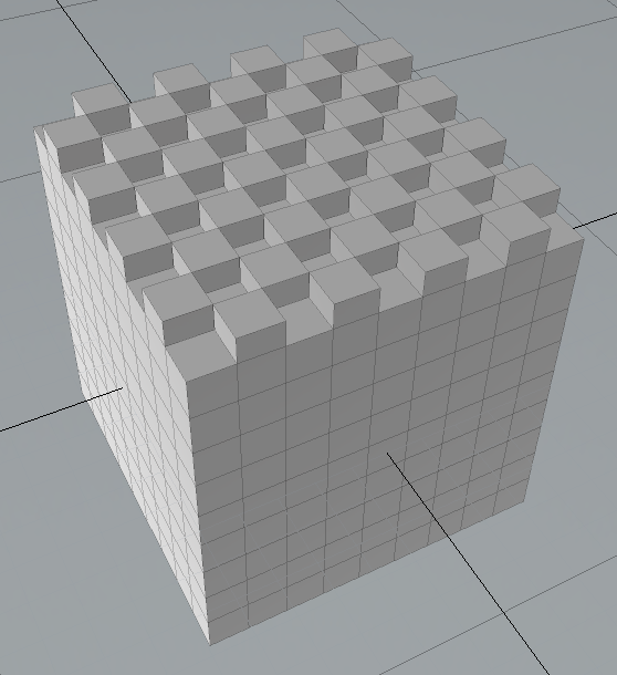
The image below shows a Polygon Bevel using the Select By Range operation. The Start index is 0, the End index is 80, and the Step value is 2.
Select by Range Properties
The following options are available for this selection node:
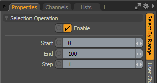
• Start - Specifies the first element in the range.
• End - Specifies the last element in the range.
• Step - Determines the step value over the range. For example, a value of 1 means that every value between the Start and End values is in the range, whereas a value of 2 means that every other value is in the range, and so on.
Select by Hard Edges
Use this selection operation to select all hard or soft edges on a geometry.
To learn how to create hard edges procedurally, see Procedural Hard Edges.
To use this selection type:
| 1. | Add the mesh operation you want to apply to the selection to the Mesh Operations list. In the Mesh Ops tab on the right panel, click Add Operator, then select the mesh operation. |
In this example, we use an Edge Extrude operation.
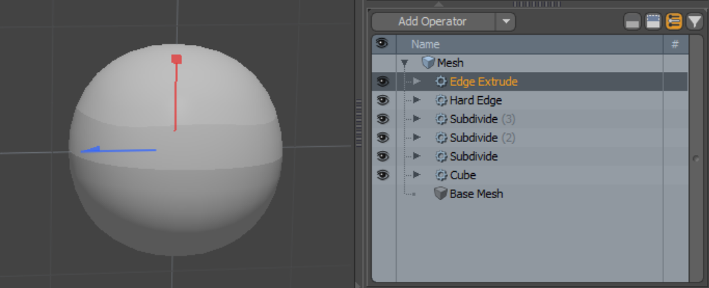
| 2. | In the Mesh Operations list, Expand the Edge Extrude to reveal its Selection input. Expand Selection too, and click (Add Selection). |
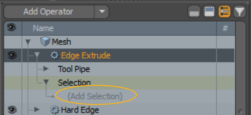
This opens the Add Mesh Operation dialog.
| 3. | Under Modifier Mesh Operations > New > Selection, double-click Select by Hard Edges. |
The mesh operation's selection input is populated with the Select by Hard Edges operation. If you now start using the mesh operation, it will only affect the hard edges.
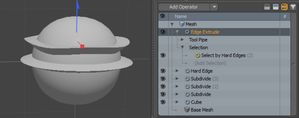
To select the soft edges of a mesh only:
| 1. | Select the Select by Hard Edges operation in the Mesh Operations list. |
Its properties are displayed in the Properties tab in the lower right panel.
| 2. | Set Type to Soft. |
Now the selection applies to all soft edges on your mesh.
Select by Hard Edges Properties
This selection type has the following properties.
|
Option |
Description |
|
Enable |
Enables or disables Select by Hard Edges. |
|
Invert |
Inverts a single selection operation or all selected operations in the Mesh Operations list. |
|
Blend Mode |
Affects the blending between different layers of the same effect type. The following options are available: • Override - The default behavior. The current selection overrides all selection operations below it in the Mesh Operations list. Previous selections are discarded and the new selection is used instead. • Add - Adds a new selection to the previous selection. Elements are treated as deselected if they are deselected by all selection operations in the Mesh Operations list. • Subtract - Removes any elements that are selected by the selection operation from the previous selection. • Multiply - Only selects elements from the new selection operation that are also selected by the first, filtering the previous selection. |
| Type | Specifies whether the selection applies to Hard or Soft edges. |
Select by Selection Set
This selection operation marks any elements that exist within a specified selection set. Combined with the Assign Selection Set mesh operation, this allows selection to be stored and then later used further up in the Mesh Operations list. For details on assigning selection sets, see Selection Operations.
Note: The selection set should be defined first, before adding the operation you want to use it with. So the Assign Selection Set operation should be below the other operation in the Mesh Operations list.
Select by Selection Set Properties
The following options are available for this selection node:
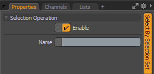
• Name - Specifies the name of the selection set to use.
Selection Operators
Selection Operators are a special kind of selection operation that test the element selection using an external Modo rig with customizable rules.
On each selection operator, the information about the element is provided as an output channel. For example, on the Polygon Selection Operator, information such as the position, normal, area, and index is provided as a channel, and a single input channel called Selection allows the selection state to be driven by a rig.
You can build any kind of Modo rig to take the output values from the selection operators, and determine the input value, specifying whether selection should be performed. When the selection operator is evaluated, the rig is evaluated for each mesh element and a different selection state can be returned for each element.
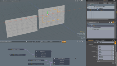
The example below guides you through setting up a simple rig using a Polygon Selection Operator. A Polygon Bevel operation is applied to polygons on a toroid, but only the ones facing the camera are selected.
| 1. | Add a toroid to your scene from the Basic sub-tab of the Model toolbox, and subdivide it by pressing D on the keyboard for a more visible effect. |
| 2. | Go to the Setup layout, select the camera item in your scene, and in the Schematic viewport, click Add Selected to add it to the viewport. Then drag its World Position channel to the Schematic from the Channels list on the right. |
Note: To make sure that the camera always faces the toroid, select your camera item and toroid, and in the camera's Properties, click Set Target.
| 3. | In the Mesh Operations list on right side of the interface, add a Polygon Bevel by clicking Add Operator, and under Mesh Operations > Polygon, double-clicking Polygon Bevel. Adjust the Shift amount by using the handles in the 3D viewport, or by editing the tool's Properties. |
| 4. | Expand the Polygon Bevel operation in the list to reveal its Selection input, then click (Add Selection) and in the Preset Browser, click Selection Operator: Polygon. |
This turns off the effect of the Polygon Bevel, as nothing is selected at this point.
Tip: If a Mesh Operation is selected, Shift+S opens the Add Selection Operator panel. Shift+F opens the Add Falloff panel. `(backtick) opens the mesh operation tree.
| 5. | Add the Selection Operator to the Schematic viewport, then double-click its diamond connector to show the connected Polygon Bevel operation. |

| 6. | Add the Selection Operator's Position X, Y, Z and Normal X, Y, Z channels to the Schematic by dragging them in from the Channels list. |
At this stage, the Schematic viewport looks like this:

Now that we've added the camera, the Polygon Bevel, and the Selection Operator, we have to calculate the angle from the geometry to the camera.
| 1. | In the Schematic, add two Matrix Constructs by clicking Add... at the top of the viewport, then under Channel Modifiers > Matrix, double-click Matrix Construct. |
| 2. | Add the Vector Maths:Add node, then connect the Position and Normal channels of the Selection Operator to the Vector A and Vector B channels of the Add vector respectively, to add them together. |
You have the following connections in the Schematic now:
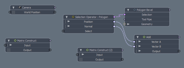
| 3. | Connect the Add node's Output to the first Matrix Construct's Input, then connect the Selection Operator's Position channel to the other Matrix Construct's Input. |
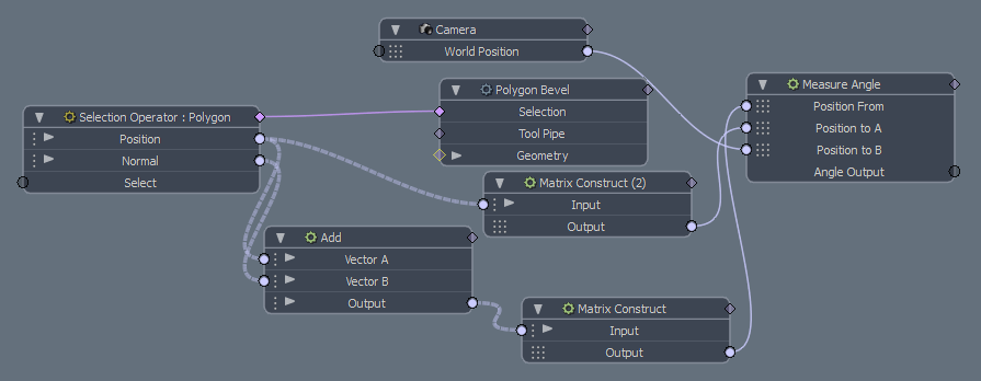
| 4. | Add a Measure Angle channel modifier to the Schematic, and make the following connections: |
• First Matrix Construct's Output channel to Measure Angle's Position to A.
• Second Matrix Construct's Output channel to Measure Angle's Position From.
• Camera's World Position channel to Position to B.
The Schematic at this point looks like this:
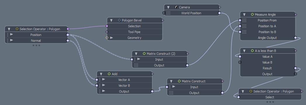
Next, we add a conditional node that we can use to select polygons which have an angle of less than, say, 45 degrees.
| 1. | Optional: To be able to drive the selection, and to make the connections a bit clearer: separate the Selection Operator's Select channel by right-clicking on it and clicking Separate Channel. |
| 2. | Click Add... at the top of the Schematic viewport, and under Channel Modifiers > Conditional, double-click Logic:A is less than B. |
| 3. | Connect the Measure Angle's Angle Output to the conditional node's Value A channel, and connect the conditional node's Result Channel to the Selection Operator's Select channel. |
| 4. | Select the A is less than B conditional node, and in the Channels list on the right side of the interface, set Value B to 45. |
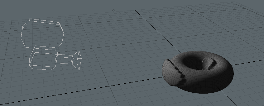
Modo now bevels the polygons that are facing the camera. As you move the camera around, or change the angle value, the affected area changes.
The images below final result in the 3D viewport and the corresponding Schematic:
Selection Operator Channels
|
Name |
Type |
Description |
Minimum |
Maximum |
|---|---|---|---|---|
|
Selection Operator: Edge |
||||
|
Index |
Integer |
The index of the edge in the mesh. |
0 |
|
|
Position |
Vector XYZ |
The edge position. |
|
|
|
Normal |
Vector XYZ |
The edge normal. |
|
|
|
Length |
Distance |
The distance from one vertex on the edge to the other. |
0.0 |
|
|
Angle |
Angle |
The angle between the two polygons connected to the edge. |
0.0 |
360.0 |
|
Is Border |
Boolean |
Outputs true if the edge is on the boundary of a polygon island. |
False |
True |
|
Vertex A |
Vector XYZ |
Provides the position of the first vertex in the edge. |
|
|
|
Vertex B |
Vector XYZ |
Provides the position of the second vertex in the edge. |
|
|
|
Selection Operator: Polygon |
||||
|
Index |
Integer |
The index of the polygon in the mesh. |
0 |
|
|
Position |
Vector XYZ |
The centroid position of the polygon. |
|
|
|
Normal |
Vector XYZ |
The polygon normal. |
|
|
|
Area |
Distance |
The area of the polygon. |
0.0 |
|
|
Flatness |
Percent |
The polygon flatness, determined by how coplanar a polygon is. |
0.0 |
1.0 |
|
Vertex Count |
Integer |
Outputs the number of vertices that define the polygon. |
2 |
|
|
Is Border |
Boolean |
Outputs true if the polygon is on the boundary of a polygon island. |
False |
True |
|
Selection Operator: Vertex |
||||
|
Index |
Integer |
The index of the vertex in the mesh. |
0 |
|
|
Position |
Vector XYZ |
The vertex position. |
|
|
|
Normal |
Vector XYZ |
The vertex normal. |
|
|
|
Edge Count |
Integer |
The number of edges connected to this vertex. |
0 |
|
|
Is Border |
Boolean |
Outputs true if the vertex is on the boundary of a polygon island. |
False |
True |
|
Select |
Boolean |
Specifies whether the mesh element should be selected or not. |
False |
True |
Modifying Selections
You can use procedural selection modifiers to change your selection, similarly to traditional selection modifiers. They are selection operations that take the previous selection and modify it. You can convert polygon to boundary selection, grow, shrink, or invert your selection.
Note: For more information on traditional selection modifiers, see Using Selection Modifiers.
Boundary Edges
This selection modifier converts a polygonal selection into an edge selection by using the boundary of the polygon selection to determine the edges to select.
You can add this selection operation above the selection you want to modify in the Mesh Operations list:
| 1. | Add a mesh operation that has a selection input, then add a selection operation to it, as described in Procedural Selection. |
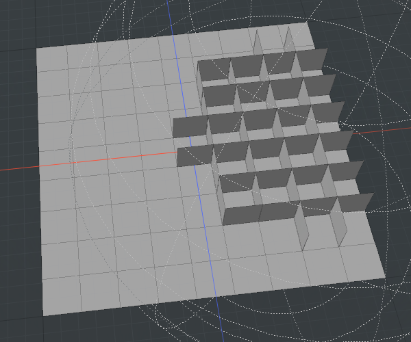
The image below shows Edge Extrude applied to a plane using a Select By Falloff selection operation with a Radial Falloff.
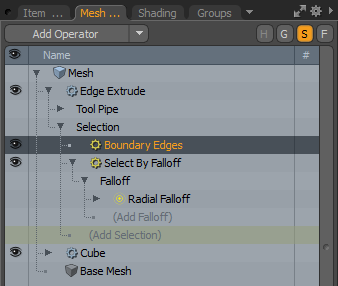
| 2. | Add a Boundary Edges selection operation to the list, then drag it above the selection you want to modify in the Mesh Operations list: |
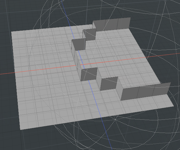
This selects all the edges that were the boundary of the previous selection:
Growing and Shrinking Selections
You can increase or decrease your selection using the Grow/Shrink selection operation.
| 1. | In the Mesh Operations list, add the selection above the selection operation you want to modify. |
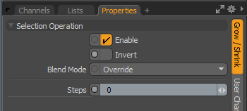
| 2. | In the Grow/Shrink operation's Properties panel, increase or decrease the Steps value to grow or shrink your selection, respectively. |
Inverting a Selection
Modo allows you to invert a single selection operation, or all selection operations in the list.
To reverse a single selection operation, in the selection operation's Properties panel, enable the Invert checkbox.

To reverse a list of operations, use the Invert selection modifier. Place it above the selections you want to invert in the Mesh Operations list.
Using Multiple Selection Operations
You can add multiple selection operations to a mesh operation and specify how Modo should evaluate them. When you add a selection operation to the Mesh Operations list, its properties are displayed in the Properties panel under the list.
Blend Mode allows you to specify how Modo treats the preceding selections.
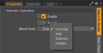
Adding a Select by Falloff (using a Linear Falloff) and a Select by Border selection operation produces the following results:
|
Blend Modes |
||
|---|---|---|
|
|
Override |
The default behavior. The current selection overrides all selection operations below it in the list. Previous selections are discarded, and the new selection is used instead. |
|
|
Add |
Adds the new selection to the previous selection. Elements are treated as de-selected if they are de-selected by all selection operations in the list. |
|
|
Subtract |
Removes any elements that are selected by the selection operation from the previous selection. |
|
|
Multiply |
Only selects elements from the new selection operation that are also selected by the first, filtering the previous selection. |
