Mesh Info Modifier
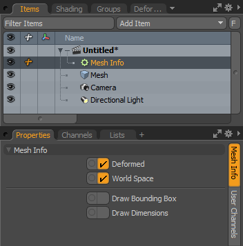
The Mesh Info modifier allows you to query information about a connected mesh. It outputs the bounding box, surface area, number of elements, and so on. This information can be queried in world space or local space, and has options to query the base mesh or the deformed mesh.
Drawing options are provided, allowing the axis-aligned bounding box of the mesh to be drawn, along with dimensions along the three main axes.
To insert a Mesh Info modifier, follow the steps below:
| 1. | In the Setup layout, click the Modifiers sub-tab on the left and then select Add Channel Modifier.... |
The Create Modifier window opens.
| 2. | For Type, select Geometry > Mesh Info. |
The Mesh Info channel modifier is added to your scene.
You can also insert the Mesh Info modifier in the Schematic viewport, by clicking Add... on top of the viewport, and selecting Geometry > Mesh Info.
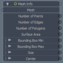
Along with the following channels, a relationship graph input is provided on the node, allowing any standard Mesh Item to be connected.
|
Name |
Description |
|---|---|
|
Deformed Mesh |
Specifies whether the deformed mesh should be queried for its properties. If disabled, the properties of the base mesh are returned. |
|
World Space |
When enabled, the bounding box is evaluated with any item transforms on the mesh taken into account. When disabled, the bounding box is returned as if the mesh is at the center of the world. |
|
Number of Points |
Outputs the number of points on the connected mesh. |
|
Number of Edges |
Outputs the number of edges on the connected mesh. |
|
Number of Polygons |
Outputs the number of polygons on the connected mesh. |
|
Surface Area |
Outputs the surface area of the connected mesh. |
|
Bounding Box Min |
Outputs the minimum vector of the axis-aligned bounding box. |
|
Bounding Box Max |
Outputs the maximum vector of the axis-aligned bounding box. |
|
Size |
Outputs the size of the bounding box. This is the distance from the Bounding Box Min to the Bounding Box Max. |
|
Center |
Outputs the center of the bounding box. |
|
Draw Bounding Box |
When this option is enabled, the calculated bounding box is drawn in the GL viewport. Note: You can override this drawing using the standard Draw channel, available on all channel modifiers. |
|
Draw Dimensions |
When this option is enabled, the dimensions of the calculated bounding box are drawn in the GL viewport, along the three main axes of the bounding box. Note: You can override this drawing using the standard Draw channel, available on all channel modifiers. |