Probe Modifiers
Channel Probe
The Channel Probe is primarily used to simplify assemblies. For example, suppose you have an assembly that requires multiple channels from a camera in order to work. In order to use the assembly, you would normally have to link up each required channel from the camera you want to use. Using a Channel Probe in the assembly saves time, requiring just one item link for the camera to allow the assembly to read as many channels as it needs.
The Channel Probe works with the internal name of custom channels, not the user name. If the probe has a custom channel with the same name as a channel on the source item, the value of the custom channel is driven by the channel value of the source. The custom channel's user name is set to match the user name of the source channel, so to see the internal name you may need to check command history.
To add a Channel Probe, do the following:
| 1. | Navigate to Animate > Add Channel Modifier > Probe and select Channel Probe. |
| 2. | Select channels on the source item, either from the Properties or the Channels list. |
| 3. | Add the selected channels to the probe using Add Selected Channels button in the probe Properties. |
The selected channels are automatically created on the probe, and the probe is linked to the source item.
| 4. | Once the probe and source item are linked, you can: |
• Add channels - you can add more channels to an existing probe by selecting the channels on the source item and using the Add Selected Channels button in the Properties.
• Remove channels - you can remove channels by deleting the custom channels from the channel probe.
• Change the source item - the channel probe item has a schematic connection point for a source item. This is automatically set when channels are added, but can be altered to point to a different source item.
Curve Probe
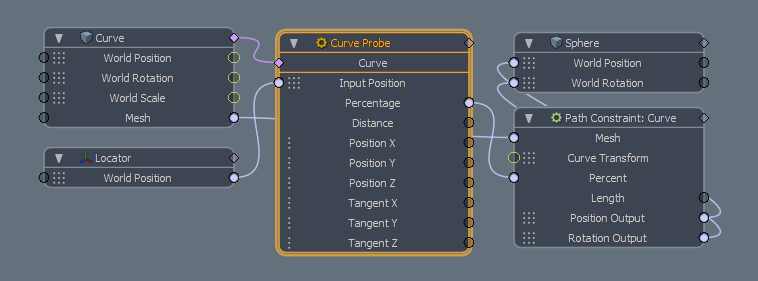
With the Curve Probe Channel Modifier you can sample various attributes from a target curve and apply the sampled value to another channel's input. This could be useful, for instance, to constrain an object along a path without actually using a Constraint modifier or, for Shading, you could use this to create adjustable seams when used with displacements.
When used in a rigging/animation context, you use a Locator item as the Input Position (sampling) and connect its World Position matrix to the probe's Input Position matrix. When used this way, the value generated by the probe represents the closest position along the nearest curve to the Locator. Modo constantly updates the output value as the Locator item moves. When used in a shading context, use a Matrix Construct modifier to convert the Texture Coordinates channel from a Texture Locator into the Probe's Input Position for it to be read on a per-sample basis.
Curve Probe
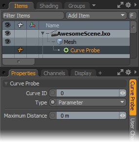
Curve ID: Modo uses this value to designate a specific curve, based on its ID, within an item layer that has multiple curves. When you set the value to -1, Modo probes all curves. Modo tags curves generally in the order they are created, starting with the first curve at id 0.
Type: This controls how to evaluate the curve. If you select Fraction, Modo evaluates the curved based on its overall length to produce a value as a fractional amount of that total. By selecting Parameter, Modo evaluates the curve based on the locations of the vertices that define it. For example, with a curve of three points, the 50% position would be the middle vertex — even if it was near the first vertex.
Maximum Distance: This defines an area around the curve for evaluation. If the distance from the point being evaluated is greater than the distance to the bounding box containing the curve plus the maximum distance, then Modo skips the evaluation for that curve.
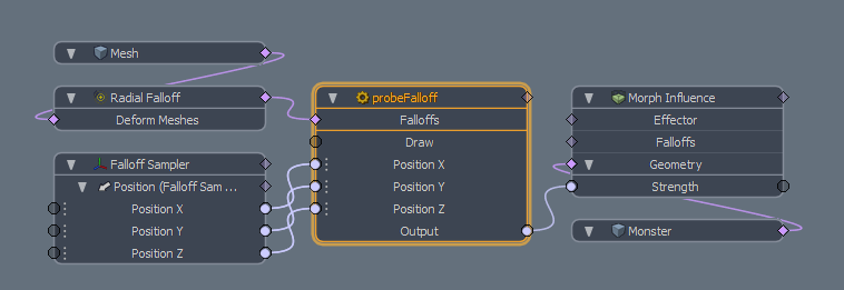
Falloff Probe
With the Falloff Probe Channel Modifier, Modo samples the value returned from a falloff based on the sample position. When used with a falloff, connect the probe to the falloff's graph connection on the node and the XYZ position to the appropriate Locator item channels. The Output channel returns a 0 to 1 value that is the falloff multiplied at that location.
Position X/Y/Z: Links the World Position transform channel of a 3D item or the Position transform output of another Channel Modifier item into this channel.
Output: This represents the strength value of the falloff at the sampled location and can be connected to any single numeric value input channel.
Falloff Probe
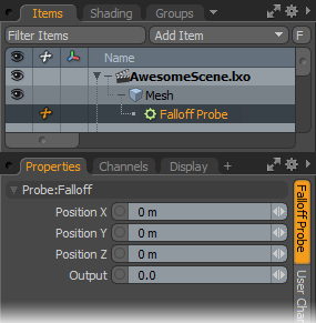
Position X/Position Y/Position Z: These values define the sampling point of the falloff. You can manually enter values to define the location in 3D space or connect the Position inputs of the node to the Position outputs of a Locator.
Output: This value represents the sampled value from the falloff. It is usually connected to the input of another node as a driver of the channel.