Cube
The Cube primitive provides a simple method for creating boxes or cubes.
To activate a tool, click the Cube icon. You can then place the primitive in your scene in a number of ways:
• Click and drag in the 3D viewport to create the initial plane for the primitive, then adjust the dimensions using the tool handles in the 3D viewport.
• To drag out a uniform-sized primitive, hold Ctrl while dragging in the 3D viewport.
• Click the primitive's icon to activate the tool. In the item's Properties tab, edit the properties, then click the Apply button at the bottom of the panel.
• Ctrl+click a primitive's icon to place a unit primitive in your existing mesh layer.
• Shift+click a primitive's icon to create a unit primitive in a new mesh layer.
Note: You can also add the same primitives from the menu bar, by clicking Item > Primitive > Cube.
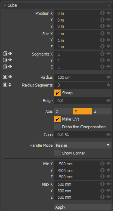
Cube Properties
|
Cube |
|
|---|---|
|
Position X, Y, Z |
These three values establish the 3D location for the center of the cube. |
|
Size X, Y, Z |
These three values are used to establish the dimensions of the cube. Set to 1 m, 1 m, 1 m (by default), this option provides us with a 1-meter cube. If you want to create a 6-foot plank that is 2 inches by 4 inches, you can type into the X, Y, and Z numeric fields 6' 2" 4",respectively, and Modo performs the measurement translation to the current unit mode (Metric, SI, or English). |
|
Segments X, Y, Z |
By default, the primitive box uses a single segment on each axis. By increasing this value, you can increase the number of "cuts" in each side of the box. This is useful if you plan to deform the cube, as these segments act as hinges during deformation operations. |
|
Radius |
This distance value sets a curved edge amount. When radius is set to a positive non-zero value, the edge of the box is rounded off using extra segments, added to the geometry. The number of segments is determined by two additional settings: Radius Segments and Sharp. |
|
Radius Segments |
When the Radius value is set to a positive, non-zero value, additional segments are added to round the cube. The Radius Segments field allows you to set how many edges are added to smooth out the corners. |
|
Sharp |
This adds an extra set of polygons to the edge of the rounded edge so that the adjacent faces are not affected by surface smoothing. This allows the surface material to use smoothing to further round the edges without losing the flat appearance of the faces of the cube. |
| Bulge | Produces a swelling effect on the cube. |
|
Axis |
Defines the major axis for the cubes orientation. On the cube this only affects the direction of Radius Segments. |
|
Make UVs |
When this button is active a UV map is automatically generated for the geometry created with the tool. This is a very useful option if you plan to UV map the model you are creating from the primitive, as it provides a baseline UV map that you can massage later in the modeling process. In many cases, this can reduce the amount of work required to map the model. |
| Distortion Compensation |
Adjusts the aspect ratio and related area size of UV polygons to reduce the distortion in the primitives UVs. Use this option when you create a Cube that does not have equal radius values. By default, the UVs that are generated for the primitive are distorted and displayed in red and blue in the UV viewport of the UV layout. To view distortion, in the UV viewport, click Options... and then enable Show Distortion. Enabling the Distortion Compensation option reducing the distortion automatically and produced cleaner UVs. This feature also works in real-time as you edit the attributes of the primitive before committing to the final values. |
| Gaps | Specifies empty space at the boundary of the UV space or between UV parts. The UV unit is specified using a percentage value. |
|
Handle Mode |
Provides three types of behavior for corner and side tool handles: • Resize from Center - Resizes both sides of the primitive at the center, when dragging a corner or side handle. • Resize - Resizes the shape at the opposite side, when dragging a corner or side handle. • Move All - Moves the primitive instead of resizing. Tip: You can also move the shape by clicking and holding the Ctrl key when in another handle mode. |
|
Show Corner |
When enabled, displays the bounding box corner handles. |
|
Min X, Y, Z/Max X, Y, Z |
You can also define a cube, based on specific X, Y, and Z bounding box locations in 3D space, which can be specified here. This makes it easy to place a cube on the ground plane for instance by making the Min Y value 0 and the Max Y value 1m. |
Tip: The Box primitive supports symmetrical creation. When Applying Precision is activated, creating the primitive shape creates an identical version across the specified axis.