Element Move
With the Element Move tool you can quickly edit individual component elements of a mesh (vertices, edges, or polygons).
Using Element Move
You can find the tool in the Model layout's Deform sub-tab, or in the menu bar, under Edit > Deform > Element Move Tool.
| 1. | Activate the tool by clicking the Element Move button, or by pressing T on the keyboard. |
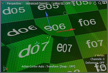
As you move the pointer in the 3D viewport, selectable elements are highlighted
| 2. | Click and drag on a vertex, edge, or polygon to move it. Alternatively, click on an element to display the transform handles, and use those to move it along an axis. |
There are two modes for the tool: Manual and Automatic. By default, the tool is in Automatic mode, and Modo determines the element type to be edited when you click. For example, if you click an edge, you edit the edge; if you click a polygon, you edit the polygon. With this tool in Automatic mode, you can edit components of the mesh independently of the current selection state.
The Manual mode forces the tool to act only on the component type defined by the current global selection mask. For example, if the selection mode is set to Vertex and the tool is in Manual mode, you can only edit vertices.
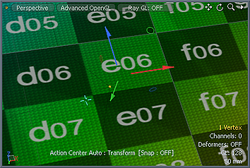
The Element Move tool also has an Element Falloff value, which creates a spherical area of influence around the element under the pointer. You can set this value in the tool's Properties panel for the tool, or by right-clicking and dragging in the 3D viewport. Modo represents this falloff in the 3D view by a yellow wireframe sphere for you to interactively adjust the region.
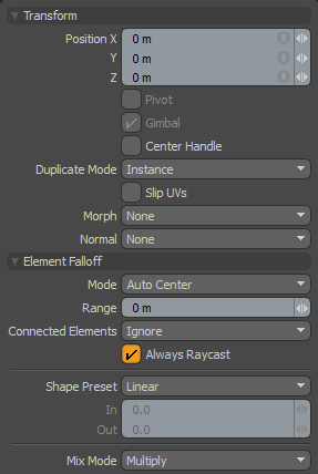
The following properties are available for the Element Move tool:
|
Transform |
|||||
|---|---|---|---|---|---|
|
Position X/Y/Z |
Displays the current offset distance. When adjusting an object interactively in the viewport, use these values as feedback for moving the element. You may specify the X, Y, and Z values to apply a specific offset distance (based on the object's position when you activated the tool). |
||||
|
Pivot |
Disabled for the Element Move tool. |
||||
|
Gimbal |
Disabled for the Element Move tool. |
||||
|
Slip UVs |
(Only available in Component modes) When enabled, edits applied to the geometry do not change the existing UV map. UV values are generally fixed to specific vertices; therefore, further edits to the geometry may warp, deform, or otherwise distort the UV values in undesirable ways. When this happens, you may need to adjust the map or to redo it altogether. To avoid this undesirable result, you enable Slip UVs so as to not disturb any existing UV mapping applied to the geometry.
|
||||
|
Morph |
(Only available in Component modes) Determines how Modo treats stored morphing information when applying transforms (such as the Move, Rotate, or Scale transforms) to geometry. There are three options for controlling how Modo deals with the morph map vertex data when applying any transforms. • None - Transforms selected (visible) morphs independent of their source, but does not affect unselected morph data. • Transform - Transforms morph data along with the base mesh. • Keep Positions - Converts morph data into an absolute morph map. All vertices retain their pre-transformed positions. Note: In previous versions of Modo, to transform a morph along with its base, you needed to select it in the Vertex Map list. If you didn't, when Modo recalled the relative morph map data, it would produce distorted, undesirable results; therefore, it was easy to accidentally spoil a model. To remedy this problem, current versions of Modo have three options to deal with the morph map vertex data. |
||||
|
Snapping |
See the Applying Snapping topic for details about this feature. |
||||
|
Element Falloff |
|||||
|
Mode |
Defines the automatic center that the transform offsets from when applied as well as the element type selected under the pointer. Auto is the default for the tool to select whatever element the pointer is over. It positions the center where the pointer intersects the surface it is modifying. Other options give you finer control. |
||||
|
Range |
Specifies a soft falloff region that attenuates the transform over the range's distance. |
||||
|
Connected Elements |
Defines what connected geometry does when you transform an element. • Ignore - Ignores all connected elements and only moves the specified element. • Use Connectivity - Affects only single-surface or connected elements. Ignores unconnected elements within range. • Rigid Connections - Moves all connected elements equally the specified distance. • Edge Loops - Moves connected loops (all the connected polygons, edges, and vertices in a single row). |
||||
|
Always Raycast |
When enabled, the tool can affect polygons in Wireframe viewport mode. When disabled, only vertices and edges can be edited in Wireframe mode. |
||||
|
Shape Preset |
Controls the strength of the falloff's influence along the extent by using a shape preset. • Linear - Attenuates the falloff evenly across its range. • Ease-In - Strengthens the falloff toward the start position. • Ease-Out - Strengthens the falloff toward the end position. • Smooth - Strengthens the falloff toward the center of the falloff. • Custom - Fine tunes the strength of the falloff based on the In and Out values. |
||||
|
In/Out |
Determines the strength of the falloff nearer to the start or end position. |
||||
|
Mix Mode |
Defines how each falloff interacts with the other(s) in instances where there are multiple falloffs applied to a transform (by using Add in the Falloff menu). |
||||