Create Intricate Patterns using Geodesic Distance Modifier
The Geodesic Weight MeshOp allows you to create a vertex map based on a mesh and a set of input points defined in an array. Through the use of locators and the Geodesic map, you can adjust the intensity of operations applied to a mesh based on the size, distance, and position of the locators.
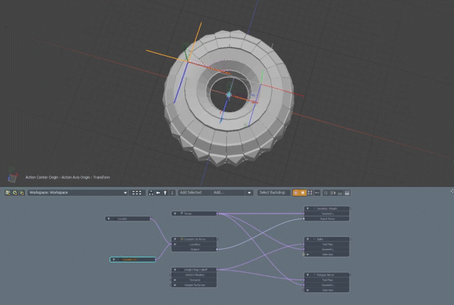
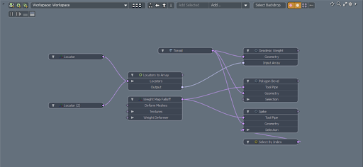
The easiest way to use the Geodesic Weight MeshOp is within the Schematic Viewport. To set up the Geodesic Weight operation:
- Open the Schematic viewport by pressing the Schematic Viewport button at the bottom of the viewport
- Bring the Geo you want the modifier applied to into the schematic viewport.
- Using the Add… button, create a Geodesic Weight node. Plug your mesh node into the Geometry input in the Geodesic Weight node.
- Create a locator by clicking Add Item in the scenes menu and navigating to Locators>Locators. Once created, drag the locator item from the items list into the schematic viewport, and then resize and place it as needed within the viewport.
- Create a Locator to Array node in the schematic viewport, and connect your locator and the Locators input in the Locator to Array node.
- Connect the Output of the Locator Array node to the Input Array parameter in the Geodesic Weight node.
- From here, you can apply whatever deformation operations you want to your mesh item; for example a poly bevel.
- Create a Weight Map Falloff once the deformations have been applied, and then plug it into the Tool Pipe inputs of your deformer nodes.
- In the properties window of your Weight Map Falloff, change the weight map parameter to Geodesic
This can be done by adding geo to the schematic viewport directly via the Add… button in the schematic viewport, or by dragging your mesh item from the items list into the schematic viewport.
Locators must be contained within an array for them to be used. However, this does mean that multiple locators can be used to drive the geodesic weight map within one array.
If multiple deformations have been applied to your mesh, you will need to plug the Weight Map Falloff into the tool pipe input of each deformer node
As the Geodesic Weight operation creates a weight map, for it to be useable it needs to be assigned to the Mesh Item via the Weight Map Falloff.
Your geodesic weight map will be named ‘Geodesic’ by default. If you have manually changed the name of your Geodesic weight map, this name change will be reflected in the list of assignable weight maps within the weight map falloff.
|
|
|
|
There are also a few options available to you within the Geodesic Weight MeshOp properties:
|
Geodesic Weight Properties |
|
|---|---|
|
Map Name |
Sets the name of the Geodesic Map to use for output |
|
Select Geodesic Map |
Set the generated Geodesic Map as the currently selected Vertex Map |
|
Normalize |
Normalizes the values in the vertex map between the input point (0.0) and the furthest point along the surface from the input point (1.0) |
|
Triangulate Mesh |
Converts your geometry into triangles when calculated, so that the distance between points can be calculated. This does not impact the topology of your mesh and is used for calculations only. If your mesh is guaranteed to be triangulated, this can be turned off |
|
Invert |
Inverts the distance values of your mesh. Your furthest point will gain a value of 1.0, while your input gains a value of 0.0 |