Symmetrize
The Symmetrize tool deletes half of the mesh and mirrors the opposite half in its place. This is useful when you accidentally lose symmetry by editing one side of your mesh item with the Symmetry Tool turned off.
|
|
|
|
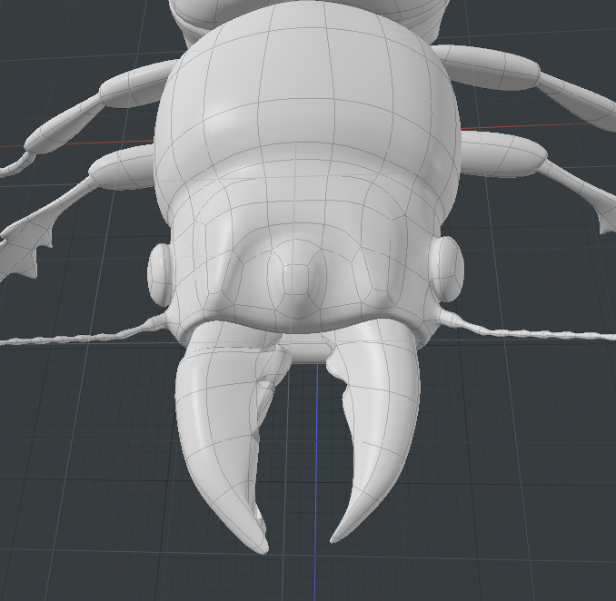
Before applying Symmetrize: |
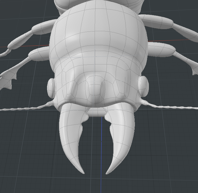
After applying Symmetrize: |
This tools works as a procedural modeling operator, a schematic operator, and as a direct modeling tool.
For more information, see Modeling Techniques.
• For direct modeling: Using the Model layout, open the Polygons tab on the left panel, and click Symmetrize.
• For procedural modeling: Using the Model layout or Setup layout, open the Mesh Ops tab, click Add Operator, and double-click Mesh Operations > Polygons > Symmetrize.
• For schematic modeling: On the top-left corner of the interface, click the schematic palette ![]() icon, click Add..., and double-click Mesh Operations > Polygons > Symmetrize.
icon, click Add..., and double-click Mesh Operations > Polygons > Symmetrize.
Applying a Direct Modeling Symmetrize Tool
The direct modeling Symmetrize tool allows you to quickly correct symmetry problems. For example, if you have beveled one side of your model and it is now non-symmetrical, you can run Symmetrize tool to correct the positional changes and geometry updates. To gain more control on how the symmetry is applied, you can also choose the axis to use, select if you want to apply a direction of negative to positive or positive to negative on the specified axis, and change other properties.
| 1. | On the top-left corner of the interface, click the |
The button displays in orange when activated.
![]()
| 2. | On the left column, expand the Cloud Assets > Meshes > Animals directory, and double-click Beetle 01. |
Note: If you have already downloaded this asset to your local drive, open the Assets > Animals directory and double-click Beetle 01.
| 3. | Close the Presets window. |
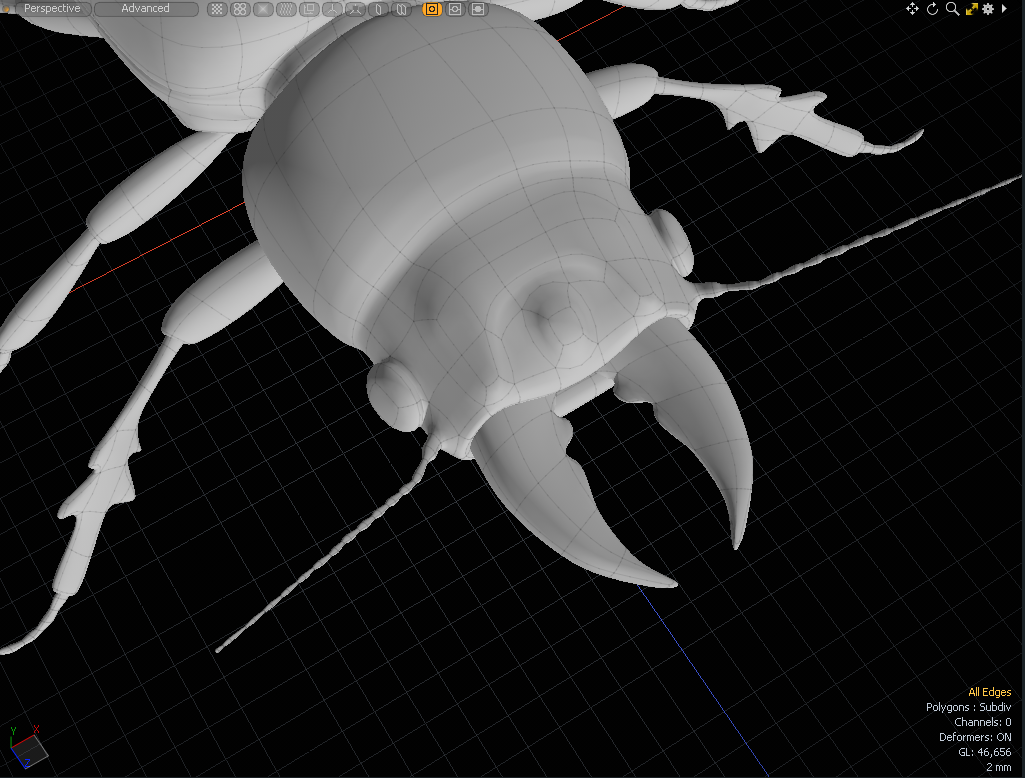
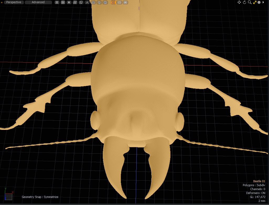
| 4. | Use your middle-mouse wheel to zoom in and press A to center the mesh item in the 3D viewport. |
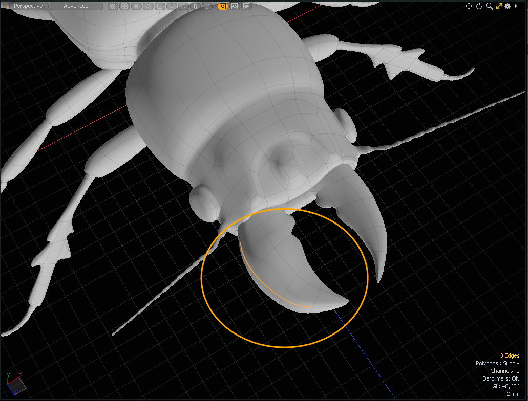
| 5. | Activate Edges selection mode and Shift+click on the outer edges of the left mandible of the beetle. |
| 6. | On the left panel, open the Deform tab, click Push, and drag along the Z axis in the 3D viewport. |
The left mandible is now wider than the right mandible on the beetle.
| 7. | Press the Spacebar twice to drop the Push tool. |
| 8. | On the left panel, open the Polygon tab, and click Symmetrize. |
| 9. | On the bottom of the left panel, set Axis to X, Direction to Positive to Negative, enable Merge, set Offset to 0, and click Apply. |
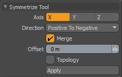
Symmetrize is applied to the beetle and both mandibles are the same size.
Applying a Procedural Symmetrize Tool
| 1. | Using the Model layout, on the right panel open the Mesh Ops tab, and click Add Operator. |
| 2. | Navigate to Mesh Operations > Polygon and double-click Symmetrize. |
Note: In the Mesh Operations list, place the Symmetrize mesh operation above the mesh you want to modify.
When added to the list, Symmetrize automatically copies the positive half of the selected mesh over the negative half. You can reverse the direction and edit other settings in the mesh operation's Properties tab. For more information, see Symmetrize Tool Properties.
Applying a Schematic Symmetrize Tool
The Symmetrize node requires the same inputs as the procedural version.
| 1. | On the top-left corner of the interface, click the schematic palette |
When activated, the button has an orange background.
![]()
| 2. | Drag-and-drop a mesh item from the Items list onto the Schematic viewport. |
| 3. | Click Add..., and double-click Mesh Operations > Polygons > Symmetrize. |
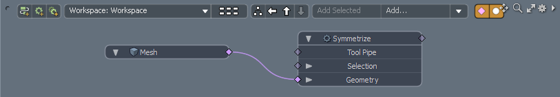
The Symmetrize mesh operation has the following inputs:
• Selection - Allows you to select the elements to which you want to apply the tool. For more information, see Selection Operations.
• Geometry - This lists any geometry that is affected by the tool. Meshes are connected automatically if they are below the tool in the Mesh Operations list.
For information about Symmetrize tool properties, see Symmetrize.
Symmetrize Tool Properties
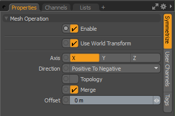
The direct modeling Symmetrize tool displays properties on the left panel. Both the procedural and schematic modeling Symmetrize tool displays properties on the right panel. Some properties may vary.
|
Enable |
Activates and deactivates the operation. |
|
Use World Transform |
When enabled, the mesh operation maintains the world transforms on the input layer, transforming any geometry inputs by the transform matrix of the input item. |
|
Axis |
Defines the axis along which to symmetrize. |
|
Direction |
Specifies the direction of the operation. The following options are available: • Positive To Negative: Deletes polygons on the negative side and mirrors the remaining polygons on the positive side. • Negative To Positive: Deletes polygons on the positive side and mirrors the remaining polygons on the negative side. |
|
Topology |
Mirrors vertex positions for topologically symmetrical vertex pairs. This does not remove half side polygons, but it moves symmetrical vertex positions based on polygon connectivity. |
|
Merge |
When enabled, merges vertices on symmetry center. Note: Merge does not work when Topology is enabled. |
|
Offset |
Offset distance of the center along the symmetry axis. |