Cel Edges
In the early days of animation, all art was hand drawn on transparent acetate called a Cel and painted with flat solid colors. This produced a unique look that is still highly desirable even today. The Cel Edges material attempts to mimic the hand drawn look of the outlines of these cartoons, creating colored strokes that follow surface contours and edges.
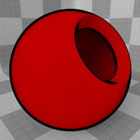
When combined with a Cel Material item, a low-fidelity cartoon-like look can be achieved. You can add the material to any surface using the Add Layer function of the Shader Tree, found in the menu under Custom Materials > Cel Edges Material.
Note: For information regarding adding and working with Shader Tree Items Layers, please see Shader Tree.
Layer Properties
|
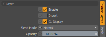
Enable |
Toggles the effect of the layer on and off. This duplicates toggling visibility in the Shader Tree. When disabled, the layer has no effect on the shading of the scene. However, Modo saves disabled layers with the scene, and they are persistent across Modo sessions. |
|
Invert |
Inverts the colors (RGB values) for the layer to produce a negative effect. |
| GL Display |
Enables or disables the drawing of the material in the 3D viewport Default mode. Disabling this can improve readability and performance when working on complex scenes. Note: Some materials, like Cel Edges, are not displayed in the 3D viewport. |
|
Blend Mode |
Affects the blending between different layers of the same effect type. With this, you can stack several layers for different effects. For more about blending, see Layer Blend Modes. |
|
Opacity |
Changes the transparency of the current layer. If there are layers below this layer in the Shader Tree, reducing this value increasingly reveals the lower layers. Reducing the value always dims the effect of the layer. |
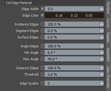
Cel Edge Material Properties
|
Edge Width |
Defined as a pixel value, this control determines the overall width of the edge stroke. Tip: You should adjust this value when changing frame resolution because a two pixel contour appears half as thick when the render resolution is doubled. |
|
Edge Color |
This value determines the color of the actual stroke. |
|
Incidence Edges |
This value determines the amount that the Incidence Edges contribute to the final Cel edge. Incidence edges are those that appear at the steepest glancing angles, perpendicular to the camera. This is useful for obtaining a more organic thick and thin stroke, as the incidence angle changes depending on the surfaces position relative to the camera. |
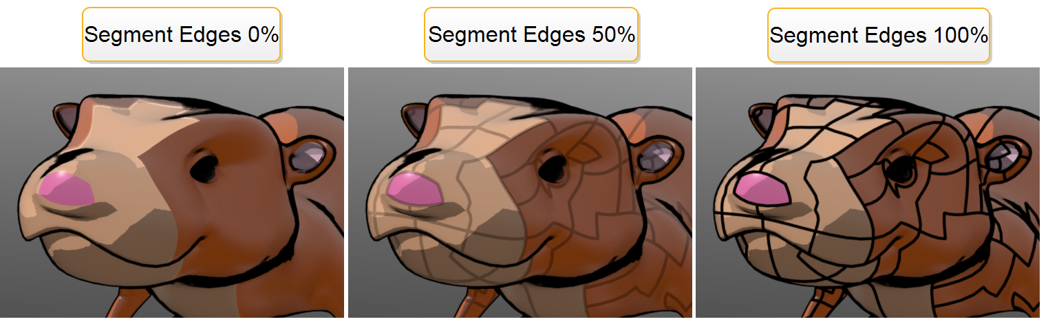
| Segment Edges |
This value specifies the percentage of cel edges to overlay with nearby surface segments. The following images show Segment Edges set to 0%, 50%, and 100% respectively.
|
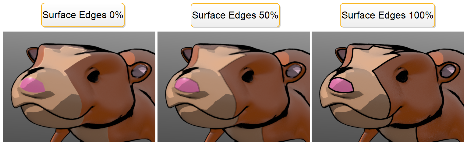
| Surface Edges |
This value specifies the percentage of cel edges to overlay with nearby material groups. The following images show Surface Edges set to 0%, 50%, and 100% respectively.
|
|
Angle Edges |
This value determines the amount that interior contour edges, within the Min and Max Angle values, contribute to the final Cel Edge. |
|
Min/Max Angle |
These two values determine the angle spread between opposing polygonal surfaces where a stroke is rendered. Typically, only an adjustment to the Max value is necessary. Lowering the value produces more contour edges and raising it produces progressively less. |
|
Distance Edges |
This function detects which interior areas of a surface are considered edges when surface contours overlap. Edges are shaded when two adjacent sampling points are greater than the given threshold. |
|
Theshold |
This value is used to determine the distance between adjacent sampling points for Distance Edges. Increasing it produces fewer interior edges for a surface, while decreasing it produces more edges. |
|
Edge Quality |
This value determines the overall quality of the Cel edges. Increasing this value produces cleaner edges, as more edge determining rays are fired, at the expense of longer render times. |