glTF Shader
The glTF (GL Transmission Format) is a file format for 3D scenes, models, materials, textures, images, articulated and skinned animation using key frame animations of transformed nodes information stored in hierarchy using the JSON standard and binary data aligned to the GL memory specifications for minimal real time run processing.
Modo supports glTF shader system directly in Modo Shader tree, the Advanced 3D (OpenGL) Viewport, the Preview Viewport, and in the glTF export plug-in. Results can be seen in the Advanced 3D (OpenGL) Viewport and the Preview Viewport. Results with the Modo glTF shader system closely relate to external real time glTF previewers.
Tip: Import textures for your glTF material using the PBR loader. See PBR Textures for more information.
Adding a glTF Material
To add a glTF material and set it as your default material:
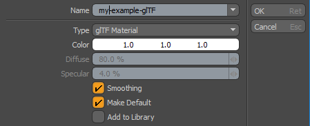
| 1. | Activate Polygons selection mode, make a selection, and press M. |
The Polygon Set Material dialog displays.
| 2. | Set the Type to glTF Material and enable Make Default. |
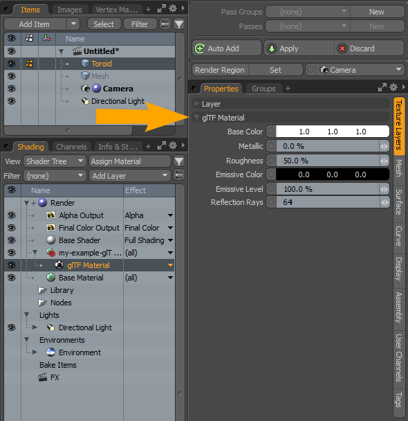
| 3. | Open the Shader tab on the right panel, and edit the properties in the Properties > Texture Layers tab. For more information, see glTF Material Properties. |
Note: For information about exporting glTF files, see Importing and Exporting File Formats.
For information about glTF preferences, see GLTF V2 I/O
Changing a glTF Shader Type
You can quickly change the glTF shader type.
Note: For information about adding and working with Shader Tree item layers, see Shader Tree.
To change a glTF shader type:
| 1. | Open the Shading tab on the right panel. |
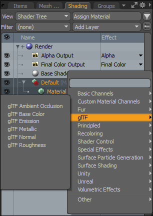
| 2. | Select the parent Material item in the list. |
| 3. | From the Effect dropdown menu, select glTF, and select a shader type. |
glTF Shader Image Effect Types
Before applying any of the glTF Shader image effect types, review the following rules.
Note: Anything outside these rules generates a warning.
• Swizzling must be on for above image map effects.
• glTF Metallic swizzling channel must be Blue.
• glTF Roughness swizzling channel must be Green.
• glTF Ambient Occlusion swizzling channel must be Red.
• Transparency Amount swizzling channel must be Alpha.
• glTF Metallic, glTF Roughness, and glTF Ambient Occlusion must have the same image clip linked in the same material group.
• glTF Base Color and Transparency Amount must have the same image clip linked in the same material group.
The following glTF Shader image effect types are available:
|
glTF Image Effect Type |
Description |
| glTF Ambient Occlusion |
Occlusion is a simple and fast way to simulate global illumination without the overhead of calculating any scene lighting, as it only takes into account surfaces and how they adjoin to each other. An occlusion map is used to indicate areas of indirect lighting Ambient Occlusion describes how cracks, crevices, corners, and other small, semi-enclosed spaces tend to be darker than surrounding surfaces under real-world lighting conditions. Their insides are occluded, so ambient light can’t get in. glTF Ambient Occlusion adds realism to views rendered and can be helpful for bringing out details when a scene isn’t supposed to have a direct light source. |
|
glTF Base Color |
The base color has two different interpretations depending on the value of metalness. When the material is a metal, the base color is the specific measured reflectance value at normal incidence (F0). For a non-metal the base color represents the reflected diffuse color of the material. |
| glTF Emission | Uses an emissive map to control the color and intensity of the light emitted by the material. |
| glTF Metallic |
Specifies the percentage of the material's electric conductivity. 0% means no conductivity (its dielectric or isolator, for example rubber, paint or wood material), 100% means full electric conductivity (material behaves like a metal). Note: Image maps with Swizzling effects glTF Metallic and glTF Roughness in a single material group must have the same Image Map linked in them. |
| glTF Normal | Uses a tangent space normal map. Geometry appears less detailed. |
| glTF Roughness |
Specifies the surface roughness of the material applied to surfaces to appear more dull or rough, or shiny and smooth. Note: Image maps with Swizzling effects glTF Metallic and glTF Roughness in a single material group must have the same Image Map linked in them. |
Exporting Skinning Animation
Meshes with applied joints with transformation animation and weight vertex maps can be exported. Each deformer group under the mesh are evaluated as separate glTF skins linking to its own Weight and Joints vertex maps contained in the skinned mesh data.
Note: Make sure you freeze any transformations you've made to your skinned mesh before exporting into glTF. Unfrozen skinned mesh transformations are ignored during import into any application that supports glTF according to the glTF v2 specifications.
• Weight map - A vertex map of weights maximally containing influences of four joints for each vertex individually for glTF v2 specification.
• Joint map - Contains indices of up to four nodes per vertex that have weight influence over vertices.
For each glTF skin there should be only one root ( armature ) joint node and all other joint nodes should be children in the hierarchy of that node. Each skin is defined by the inverseBindMatrices property (which points to an accessor with IBM data), used to bring coordinates being skinned into the same space as each joint, and a joints array property that lists the nodes indices used as joints to animate the skin.
The Save Skinned Meshes in World Space preference option should be used for skinned animation in glTF v2 for compatibility with external previewers ( for example, Babylon.js ). Enabling Save Skinned Meshes in World Space in glTF v2 I/O preferences applies a mesh transformation matrix to mesh vertices and moves them to bind position in world space. World space mesh vertices are transformed by inverse bind matrices of joints and their vertex weight influence correctly.
For more information about preferences, see GLTF V2 I/O.
Exporting Cameras
Cameras from Modo are exported fixed as perspective cameras with transformation properties and placeholder properties with Z set to the value 0.01 and Y set to the value of 0.8726.
glTF Material Properties
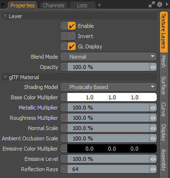
• Shading Model - Controls how light and surfacing attributes are evaluated for a final rendering.
• Physically Based - Uses highlight shape and Fresnel falloff shading. This is based on the Generalized Trowbridge-Reitz BRDF model, popularized by a number of famous movie studios because of its ability to produce realistic surface shading.
• Unlit - Defines the Base Color Multiplier used for surface shading without being affected by any type of lighting (such as Directional or Environments).
Note: The Material Transparency Amount property can also rendered when enabling the Unlit shading model.
• Base Color Multiplier - Defines an RGB value for the material's base color that is applied to the surface. When Base Color textures are applied, this parameter acts as a multiplier to the final blended texture values.
• Metallic Multiplier - Metallic colors typically spread a wide colored highlight over the surface. Specify the metal quality of the material by changing the percentage value. A value of 0 specifies a non-metallic surface, while a value of 1 results in a metal surface. When Metallic textures are applied, this parameter acts as a multiplier to the final blended texture values.
• Roughness Multiplier - Surfaces can be very different from each other, such as a rubber ball, a plastic cup, and a terracotta brick. These are all seemingly smooth surfaces, but on a microscopic scale their surfaces are very different. The microscopic surface variations has a direct effect on the way the light reflects off of each surface.
The Roughness setting simulates these microscopic differences making surfaces appear more dull or rough, or shiny and smooth. It also affects both the specular highlight as well as ray traced and environmental reflections. When Roughness textures are applied, this parameter acts as a multiplier to the final blended texture values.
• Normal Scale - Scales for the normal map in the Main Maps.
• Ambient Occlusion Scale - Controls the amount of occlusion applied. A value of 0.0 means no occlusion. A value of 1.0 means full occlusion. This value is ignored if the corresponding texture is not specified. This value is linear.
• Emission Color Multiplier - Specifies which part of the material should glow due to emitting light.
• Emission Level - Specifies the level of emission.
•
•
•
• Reflection Rays - This property refers to baking with F9 or Preview render. Specifies the number of rays used for sampling reflection. A higher number of rays produces better rendering quality, but increases render time.