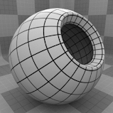
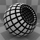
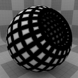
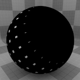
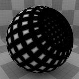
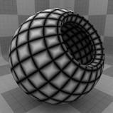
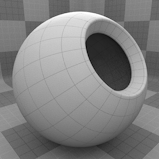
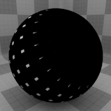
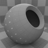
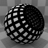
Wireframe Texture
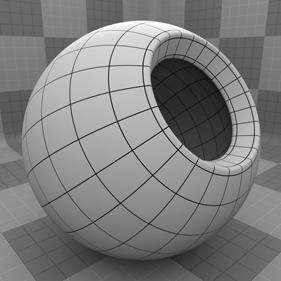
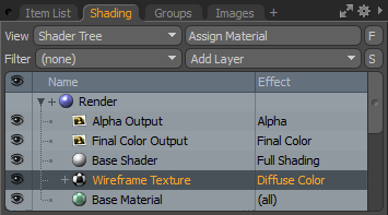
The Wireframe texture is a special type of procedural texture that can be applied to draw lines along the polygon edges of the target surface. It is useful to produce the same type of wireframe line rendering used in the 3D Viewports, but in a final rendered image. You can assign the Wireframe texture in the Shader Tree under Add Layer > Special > Wireframe Texture.
Note: The Wireframe texture cannot be applied to deforming meshes, but it can be baked into a UV mapped texture and applied to the deformed mesh.
The shader gives you control over the line color and thickness, and a selection set can be assigned to limit the lines to just a specific area of the target surface. The Wireframe texture can be applied in any way that a normal Shader Tree texture layer can be used, making it useful for other purposes as well, such as layer masks, unique displacement effects and to create interesting layer blending effects.
Note: For information regarding adding and working with Shader Tree item layer, see the Shader Tree topic.
Layer Properties
>
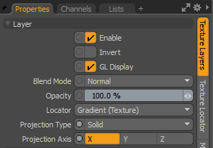
|
Enable |
Toggles the effect of the layer on and off. This duplicates the functionality of toggling visibility in the Shader Tree. When disabled, the layer has no effect on the shading of the scene. However, Modo saves disabled layers with the scene, and they are persistent across Modo sessions. |
|
Invert |
Inverts the colors (RGB values) for the layer to produce a negative effect. |
|
Blend Mode |
Affects the blending between different layers of the same effect type. With this, you can stack several layers for different effects. For more about blending, see Layer Blend Modes. |
|
Opacity |
Changes the transparency of the current layer. If there are layers below this layer in the Shader Tree, reducing this value increasingly reveals the lower layers. Reducing the value always dims the effect of the layer. |
|
Locator |
Sets the association for the Texture Locator. Most texture layers have a Texture Locator that Modo automatically creates in the Item List. This defines the mapping of the texture (how Modo applies the texture) to the surface. You can specify alternate locators, but this is normally not required. Although you may want multiple texture items to share a single locator. |
|
Projection Type |
Defines how a texture/material is applied to a 3D surface. Types vary significantly in their effects. For a guide to each Projection Type see Projection Type Samples. |
|
Projection Axis |
The texture/material is projected down this axis. This applies to Planar, Cylindrical, Spherical, Cubic, Box, and, Light Probe projection types. |
Wireframe Properties
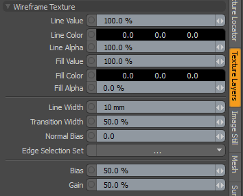
|
Wireframe Texture |
|
|
Line Value/Color |
Depending on the Effect definition for the layer, the line itself is represented on the surface by either a Value amount, such as with bump maps and specular amount values, or by a Color such as with diffuse color or reflection color. |
|
Line Alpha |
Determines the opacity of the resulting lines on the surface. At 100%, the line is fully opaque, attenuating toward 0%, where the line is fully transparent. |
|
Fill Value/Color |
Depending on the Effect definition for the layer, the fill area is represented on the surface by either a Value amount, such as with bump maps and specular amount values, or by a Color, such as with diffuse color or reflection color. By default, the Fill Alpha value is set as fully transparent so that only the lines show, rendering the fill area completely transparent by default (different from any other texture layer defaults when added) so changes to the fill might not be visible at first because of this behavior. |
|
Fill Alpha |
This value determines the opacity of the area between the lines on the surface. At 100%, the fill is fully opaque, attenuating toward 0% where the line is fully transparent. Note: By default, the Fill Alpha value is set as fully transparent so that only the lines show, rendering the fill area completely clear by default (different from any other texture layer defaults when added). |
|
Line Width |
Specifies the thickness of the line area of the texture. For examples, see Wireframe Texture Examples. |
|
Transition Width |
Defines an area of transition between the line and fill areas, defined as a percentage of the Line Width. Even when a soft edge isn't desired, a small amount can aid the anti-aliasing function, producing a smoother line. For examples, see Wireframe Texture Examples. |
|
Normal Bias |
You can use this option to flatten the wireframe shading toward the surface, reducing crosstalk from opposing surfaces in close proximity to each other. The control is activated when the Normal Bias value is greater than 0. Crosstalk artifacts can also be minimized by applying two separate Wireframe textures on each opposing surface. |
|
Edge Selection Set |
Defines an edge selection set to limit the application of the Wireframe shading to specific areas of the surface. Edge selection sets are regular selection sets made while in Edges Selection mode. Once a named set is defined, it can be applied here using the Edge Selection Set option by selecting the named set from the pop-up. |
|
Bias |
When a Transition Width amount is defined, the Bias value pushes the shading to favor more either the fill or line area of the shading, depending on the value entered. The default 50% value produces a linear transition across the defined width. For examples, see Wireframe Texture Examples. |
|
Gain |
This setting is similar to a Gamma control that affects the falloff across the transition width. Setting the Gain to 100% creates a very sharp falloff effect, whereas setting the value to 0% creates a plateau around the value or color mid-point with sharp falloff on either extreme of the gradient. This value depens on the Transition Width, as it works across the gray tones of the image. For examples, see Wireframe Texture Examples. |
Wireframe Texture Examples
|
|
|
|
|
Line Width 1 mm |
Line Width 3 mm |
Line Width 5 mm |
|
|
|
|
|
Transition Width 0% |
Transition Width 50% |
Transition Width 100% |
|
|
|
|
|
Bias 0% |
Bias 50% |
Bias 100% |
|
|
|
|
|
Gain 0% |
Gain 50% |
Gain 100% |
