Search Tips
Nuke Stage Direct Mapping project node graph rundown
This node graph maps the image sequences onto the displays. It utilizes switch nodes to quickly give you different options in playback.
How Node graphs work
Each node has a different purpose, like a building block for creating effects and manipulating images in your scene.
They are connected via pipe connections. You can build node sets up like layers via these connections. You start (normally at the top) with a node that reads the image or texture you want to edit, and each subsequent node builds onto the subset you already have. This way you can build up effects in your node graph.
All nodes found in Nuke Stage are Nodes.
Stage Left / Stage Front / Stage Right
These three node sets have the same structure to enable you to easily navigate and make changes to your different outputs. The explanations for these node sets will be broken down into the following sections:
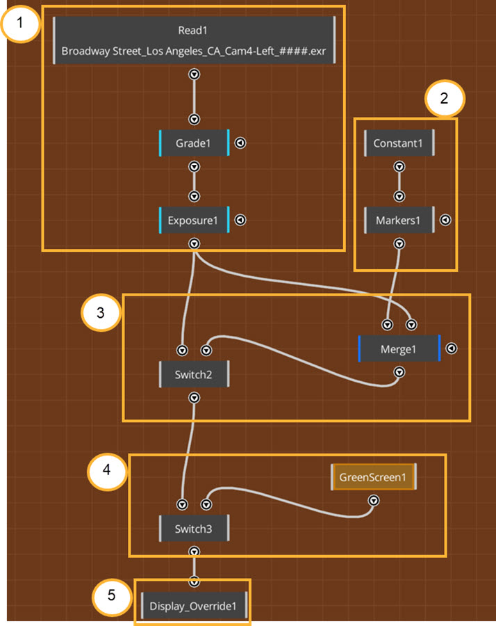
Section 1
• A Read node at the top of the node graph with an image sequence.
• This Read node is then connected to a Grade node. You can use this node to adjust the grade settings of the image sequence in the Read1 node.
• The Exposure node similarly enables you to control the Exposure settings applied to the image sequence.
Section 2
This section of the node graph includes optional testing images that you may want quick access to when setting up the stage.
• The Constant1 node will make the input one solid color. In this specific use case, the Constant node is being used to create a transparent mask for the Markers node to be placed on top of.
• This connects to the Markers1 node. The Markers node creates tracking markers to help with compositing the background of the scene in post.
Section 3
The Exposure and Markers nodes are then attached to a Merge node and a Switch node.
• The Merge node merges the two node sets that are plugged into it using the pipe connections. The Merge node has two inputs, called src0 and src1. The Merge node merges src0 into src1, and outputs this result.
In this example, the Read1, Grade1 and Exposure1 nodes are plugged into scr1, and are merged with the Constant1 and Markers1 nodes that are plugged into src0. This is done so that when the Markers and Constant nodes are applied, they will be applied to the edited image sequence.
• The Switch node enables you to switch between the two inputs, so you can change the direction the car is driving in. To use this switch node, change the Which property in the node. 0 will be one input, and 1 is the other input.
Note: The index of the Which parameter, which defines the output of the node, starts at 0.
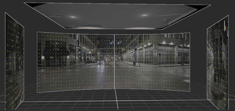
Section 4
• Switch2 feeds into another Switch node (Switch3) with another Constant node (labeled GreenScreen1). You can quickly switch between them in case you need another green screen instead of the image output.
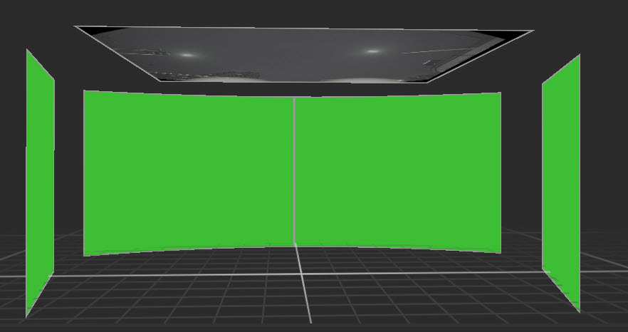
Section 5
• The Switch node is then connected to Display_Override1. The Display_Override node defines which output will directly map onto which display.
Stage Ceiling
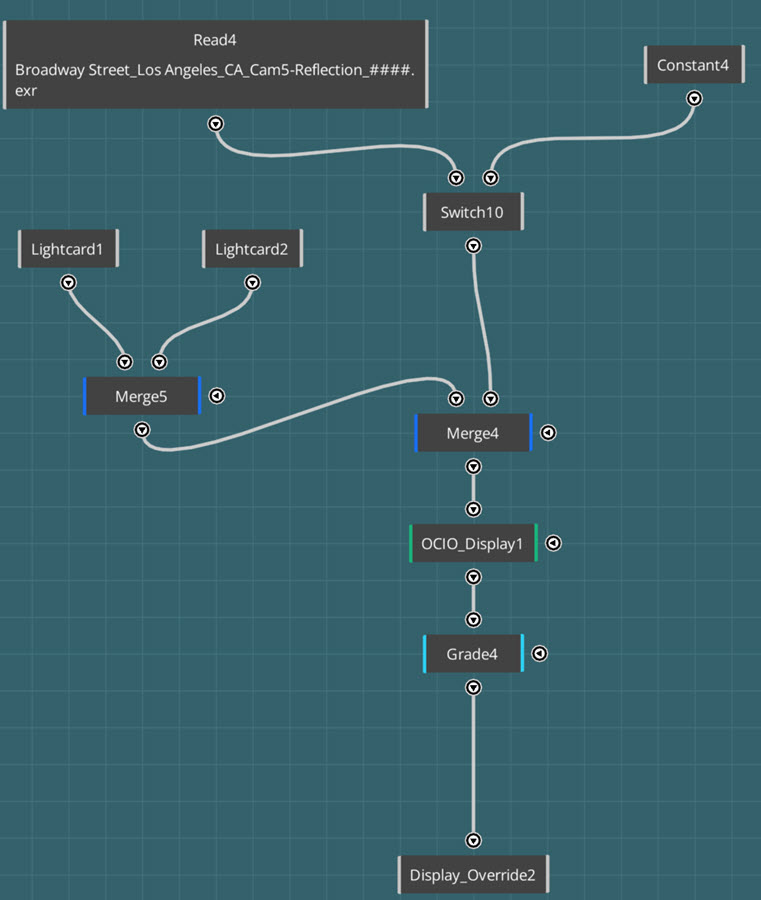
The Stage Ceiling node set corresponds to the ceiling display (Display_Ceiling) in the stage setup. Lightcards are used to emulate the effect of lamp posts in the scene, creating a more realistic environment in production as the lights move with the driving plate footage.
• The Read7 node has the ceiling image sequence, which is the sky of the scene.
• Constant4 is a blank white image you can use if you need more light in your scene.
• Switch10 enables you to switch between the ceiling imagery on the Read node and the Constant node (by changing the value between 0 and 1).
• Two Lightcard nodes are created to emulate the street lamps. These are animated in the sequencer and will create more realistic lighting in your scene.
Tip: For more information on animating sequences in Nuke Stage, go to the Working With Sequences.
• The two Lightcard nodes are then inputted to a Merge node (Merge5). Now that they are merged together, they can be treated as one input when connected to another node.
• Merge4 merges the merged lightcards with the nodes that contain the scene imagery, so the lightcards go on top of the image sequence.
• OCIO_Display1 uses the OCIO file loaded in Project Graph > Hardware > OCIO > File to change the colorspace of the image sequence. This workflow is used to ensure your colors are accurately represented on a specific display device. see more atOCIO Color Management.
• Grade4 is then added for any grading changes for your scene which can be changed live on set.
• The Display_Override2 node defines which output will directly map onto which display.