Search Tips
Nuke Stage Projection Mapping project node graph rundown
To set up this project, follow the Readme.txt file inside of the project folder.
This project has two node graphs, the USD_Texture_Graph that adds texture effects to the scene, and the Camera_Graph, which adds camera effects.
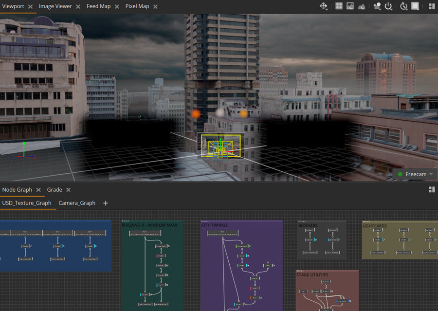
How node graphs work
• Each node has a different purpose, like a building block for creating effects and manipulating images in your scene.
• They are connected via connectors (visualized as lines between nodes). You can build node sets up like layers via these connectors. You start (normally at the top) with a node that reads the image or texture you want to edit, and each subsequent node builds onto the subset you already have. This way you can build up effects in your node graph.
• Edit node values by selecting the node in the Node Graph, and changing the properties of the node in the Properties panel.
All nodes found in Nuke Stage can be found at Nodes.
USD_Texture_Graph
City Grades
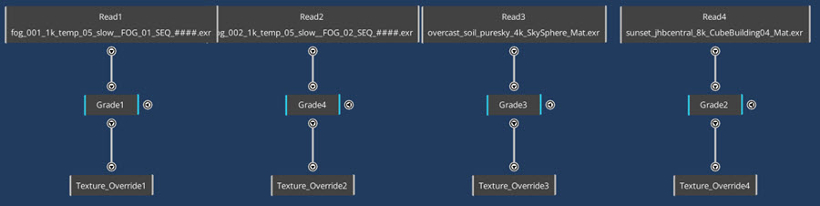
This part of the node graph contains different texture override options in the Read nodes, such as different sky coloring and fog image sequences to add atmosphere.
• Read1 and Read2 are image sequences of fog.
• Read3 is an image of a cloudy skyscape that can be manipulated to change the coloring of the sky.
• Read4 is an image of the hero building in the USD scene that enables you to edit and grade it separately.
The images in the Read nodes are defined in the Path property of the node.
Each of these Read nodes are inputted into Grade nodes, which means any grading changes you make apply to the input so will apply to the image. Using Grade nodes enable precise editing of a scene so you can get the exact results you are looking for. For example, the Gamma property of the Grade1 and Grade2 are used in this project to make the fog look more realistic within the city scene.
The Texture_Override nodes display the result of the nodes above it onto the Override target defined in the Texture_Override's Properties panel. For example, the Override target for Texture_Override1 is the FOG_01 mesh (FOG_01_SEQ_UVTexture), meaning that the override node projects onto that mesh. Any grading (or other manipulations added to the node graph) that are applied to the Read node will be visible in the final output on the scene.
Tip: Select a node and use the D hotkey to enable/disable the contents of that node. Do this on the Grade nodes to toggle the effects they apply to the Read nodes.
Building 9 - Window Mask
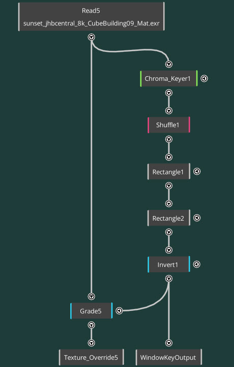
The window mask is a node-set that alters the coloring of an isolated section of the .exr file in the Read node.
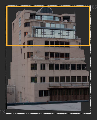
The .exr file is the building mask for the geometry, however the window reflections on this original image are the wrong color for the scene. We can use nodes to edit this specific part of the mask so that it feels more realistic to the rest of the scene.
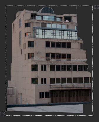
• The Read node contains the texture override path for CubeBuilding09. This texture override image will enable texture edits to be made to the prim, which is helpful for on-set compositing.
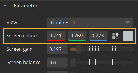
• The Read node is then connected to a Chromakeyer node. The Chromakeyer node isolates the overarching window color and makes it transparent. This is achieved by defining the Screen colour parameter of the node as the main color of the windows. You can use the color picker for this by clicking on the square color icon in the Screen colour parameter.
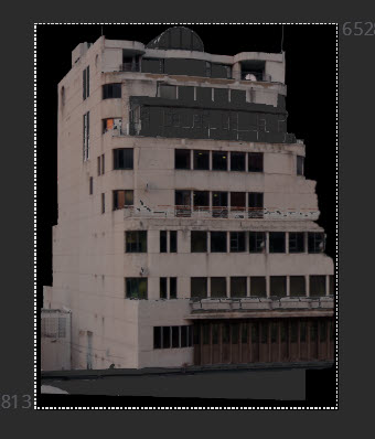
• The Shuffle node replaces all of the channels to Alpha. This makes the rest of the texture override only have Alpha information in them.
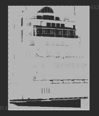
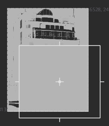
• The two Rectangle nodes, Rectangle 1 and 2, create two white rectangles that block out the areas of the building that don’t need the window mask applied to them.
Rectangle 1:
Rectangle 2:
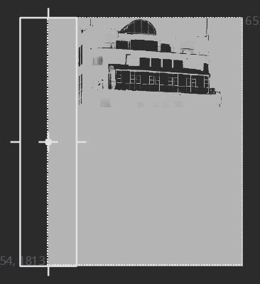
• The Invert node inverts all the color channels, so that the window mask will only apply to the white sections of the texture override. The final mask:
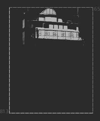
Note: You can check the mask output at Image Viewer: /USD_Texture_Graph/WindowKeyOutput
• The Invert1 node is then connected to Grade5, in the mask input. The Grade node is then applied to the mask in the sections defined in this node subset.
Tip: Disable the mask node subset and view Texture_Override5 node to see how the grade node applies without the steps of isolating the specific area for a mask.
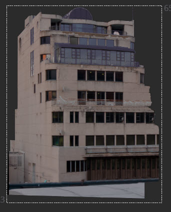
• Texture_Override5 displays the final result of the window mask applied to the building texture.
City Twinkle
This node subset creates twinkling lights to give an effect of realtime light. We achieve this by creating a mask over the traffic lights in the texture, and applying an animated noise effect.
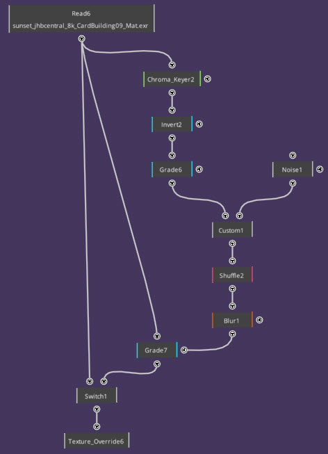
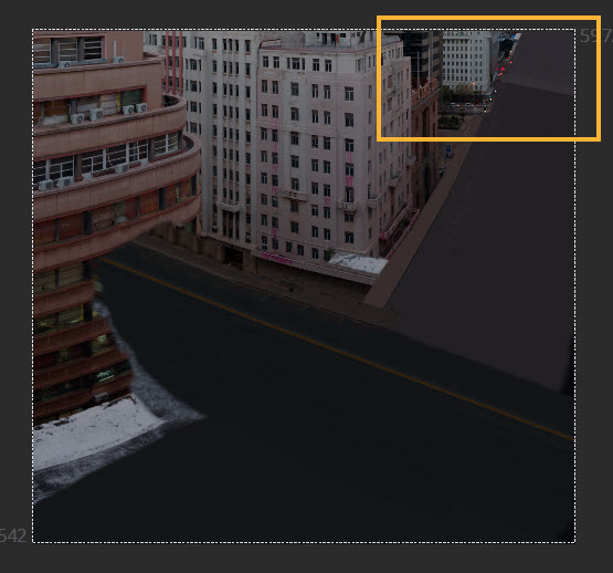
• The Read node contains the texture override image. In this example, this contains the traffic lights that the twinkle effect is going to be applied to.
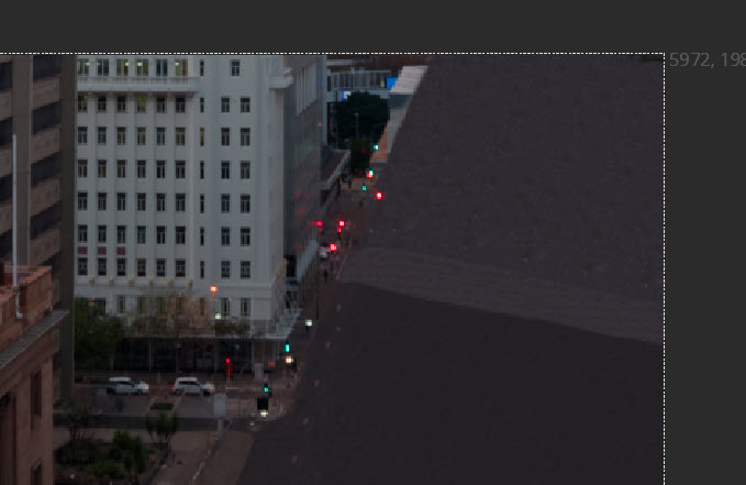
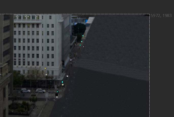
• The Chromakeyer node takes the red of the traffic light (defined in the Screen colour property) and makes it transparent in the Read node’s image.

Before Chromakeyer node:
After Chromakeyer node:
• The Invert node then isolates the areas of red as it inverts all of the color channels of the image. Because the red color was chromakeyed, it has no color data and so appears white, whereas the rest of the image turns black. This means we now have isolated areas to be able to create the mask, ensuring the twinkle effect will only be active in the specific areas we need it in.
• Grade6 boosts the white value of the section. This is a common tool to enhance the result of a mask, which is what we want to achieve here.
• The Noise1 node defines the parameters for a noise input to apply to the image.
• The Grade6 and Noise1 nodes are then merged into a Custom node. This Custom node uses GLSL code to multiply the Grade (src0) and Noise (src1) inputs so that the effect only appears in the white section of the image.
• Shuffle2 replaces all of the channel inputs with Alpha. This takes out any color data.
Before Shuffle node:

After Shuffle node:
• Blur1 blurs this twinkle effect that has been created, through the Size parameter of the Blur node. This makes the light effects more realistic and less sharp.
Before Blur node:
After Blur node:
• Grade5 makes the twinkle effect brighter on the image through the Lift and Offset parameters. The scr0 input inputs the image into the Grade node, and the mask input (on the side) controls where the grade is applied.
The Grade node on the texture without the mask input:
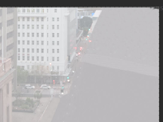
The Grade node with the twinkle mask applied:
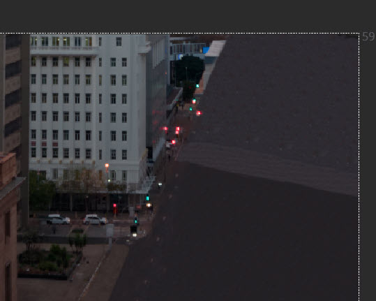
• The Switch1 node enables you to control whether the mask for the twinkle effect is active or not.
The Switch node not displaying the twinkle mask:
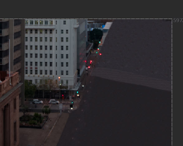
The Switch node displaying the twinkle mask:
• The Switch1 node enables you to control whether the mask for the twinkle effect is active or not.
• Texture_Override6 defines the override target as CardBuilding09, meaning the above effects will be applied to that specific texture.
Blockers and Lightcards
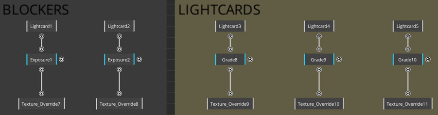
You can use Lightcard nodes to create blockers (also known as flags in production). These can be helpful when you want to control the lighting in a specific area in your scene.
• The Lightcard nodes in the Lightcards section are set to Radial mode, and Kelvin color mode. They each emulate a different temperature of light. They also each have a Grade node that can make further adjustments without altering the Kelvin temperature. For example, you can use the Gain property to bring the intensity of the lightcard up or down.
Each of the Lightcard nodes are connected to Texture_Override nodes for their outputs. The Texture_Override nodes display the final effect of the node set on the texture defined in the Override target.
• The Blockers are created using Lightcard nodes with their Mode property set to Rectangle. They are then attached to Exposure nodes, which enable you to adjust the exposure using stops.
Stage Utilities
The Stage utilities node subset gives you different options for common VP backgrounds.
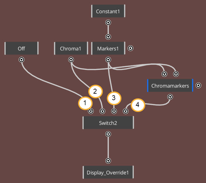
The Switch node
The Switch node is a node that enables you to switch between different node subsets. You can create multiple inputs for the Switch node, and then attach the switch node to the Display_Override node.
Note: The index of the Which parameter, which defines the output of the node, starts at 0.
Only the node subset you select to be the output will display on the wall. In this example, there are four options to switch between.
Option 1
Choosing this option (0 in the Which parameter) will mean there are no effects added to the wall.
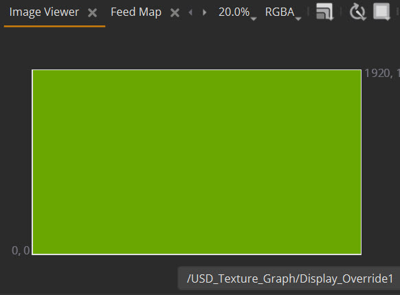
Option 2
Choosing this option will add a green screen effect to your wall. Defined in the Colour parameter of the Constant node (which is labeled Chroma1 in this graph).
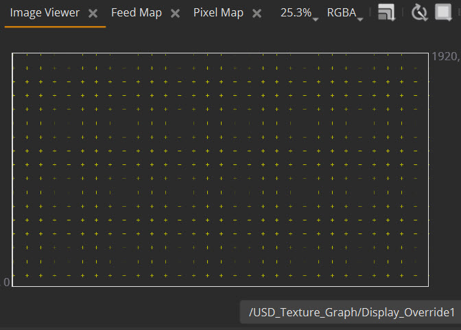
Option 3
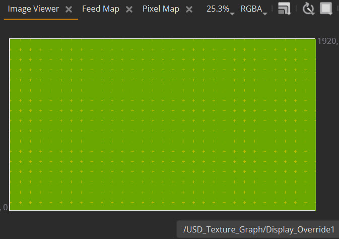
For this option, the Constant node creates a transparent layer. A Markers1 node is then plugged into the constant node, so that the markers will sit directly on top of the camera render already displaying on your wall.
Option 4
This option is made out of both the Chroma and the Markers1 nodes. Both the Chroma and the Markers1 node are attached to a Merge node (labeled ChromaMarkers). This makes the markers sit on top of the green screen.
Camera_Graph
Inner Cam
Section 1
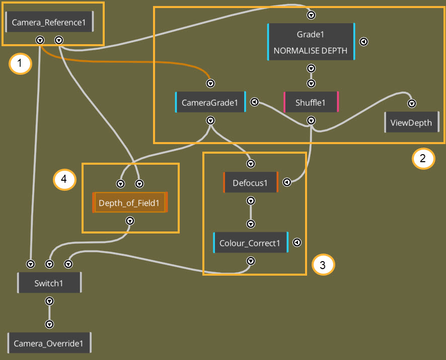
• The Camera_Reference1 node is the image that is being rendered by the camera. In its Camera parameter, InnerCam is defined. It has a connector from its render output port going directly into a switch node, which enables you to view the camera render without any of the depth effects added to it. It's depth output port is connected to depth-creation node sets outlined in the following sections.
Section 2
• Camera_Reference1 is also connected into Grade1, which is labeled NORMALISE DEPTH. This is where you set your depth map by setting the Blackpoint property. This is so you can control which parts of your scene are blurred (white) and which are in focus (black).
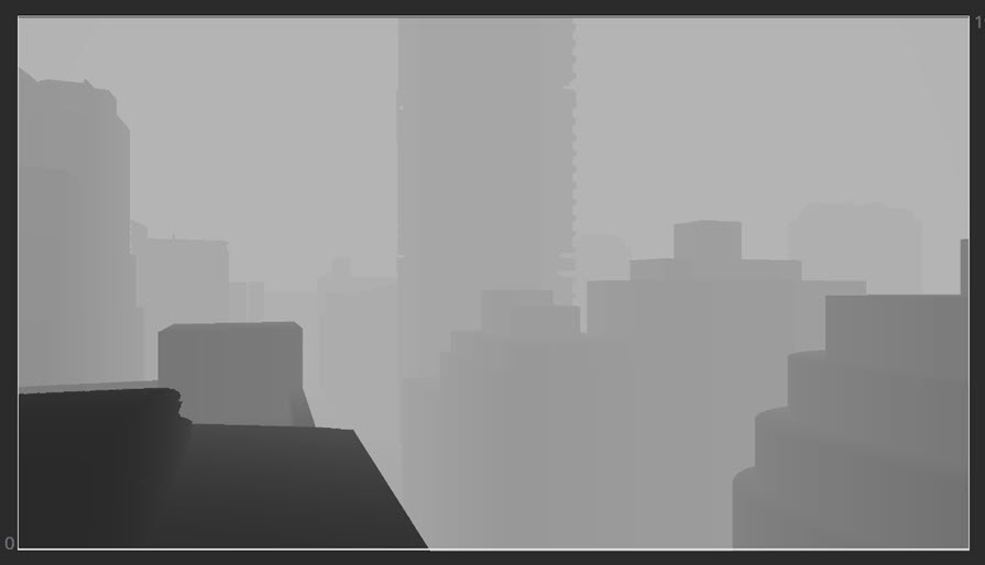
• The depth data coming from the Camera_Reference node is in the RGB color channels, and we want to use it as a mask input for other nodes (which always uses the alpha channel of the incoming image). In order to achieve this we need to use a Shuffle node to move either the red, green or blue channel data into the alpha channel. As the depth data is the same in the these three channels we'll shuffle the red channel data into the Alpha channel.
Tip: Note: In the Image Viewer, select the ViewDepth node (which is a labeled Output node) to see the depth map.
• The CameraGrade1 node can be used for depth-based grading. For example, if you wanted to create a dusty haze in your scene, this node can help that effect look realistic from a depth perspective. It can also be used for grade-based control to tweak the grading of your scene.
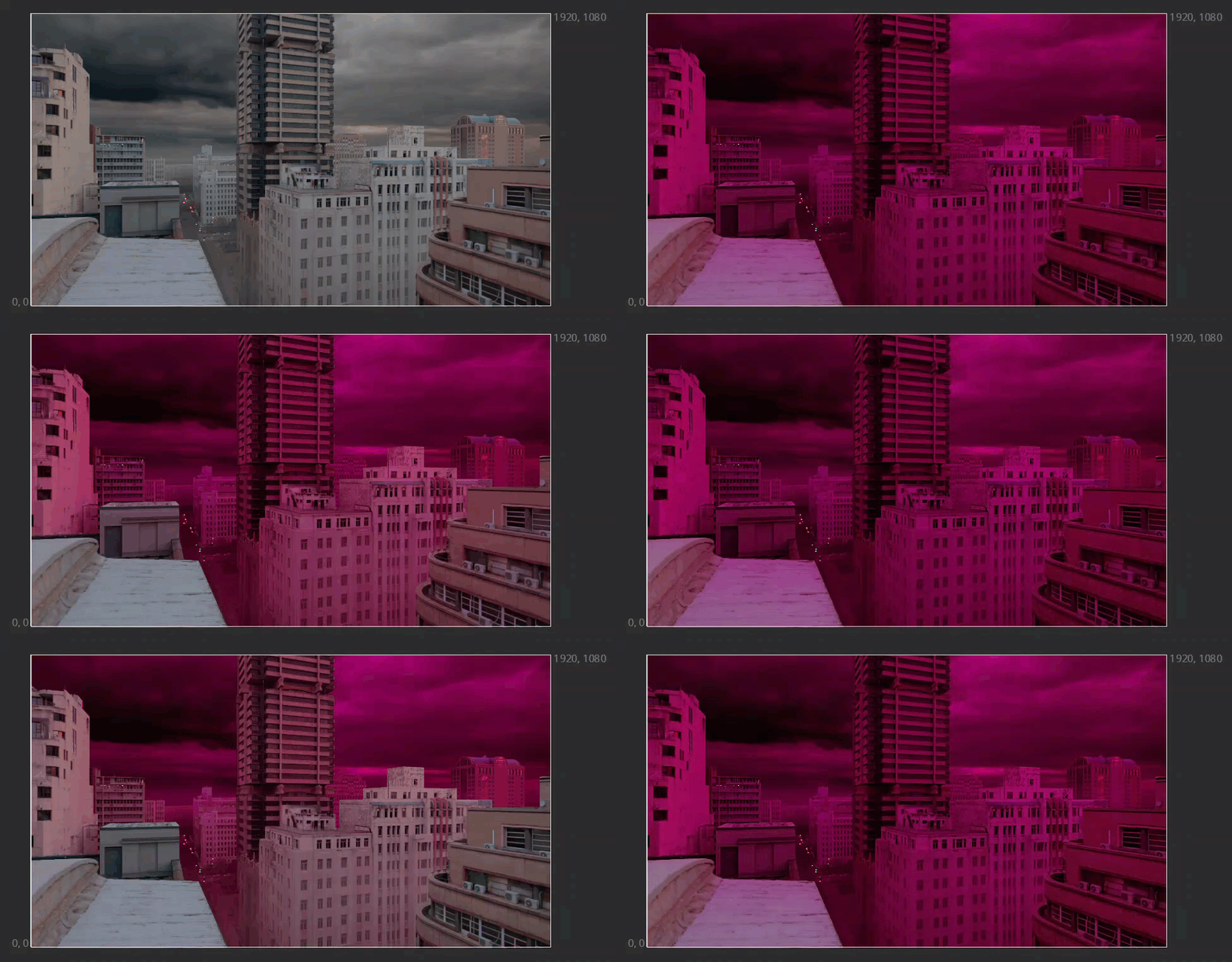
In the below GIF, the Gamma parameter in the Camera_Grade node has been changed to a pink tone, and the Blackpoint of the Grade1 NORMALISE DEPTH node is being adjusted to provide different depth-based grade effects.
Sections 3 and 4 intro
The following two sections present two different approaches to create a similar result.
• Section 3 uses a Defocus node (which is equivalent to the Nuke Defocus node) to defocus using general values to control the effect.
• Section 4 uses a Depth of Field node, which uses the depth of field based on real camera parameters (in this case, from Camera_Reference1). This option is more real-time friendly, as it produces the result faster.
Section 3
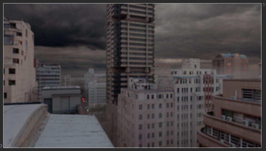
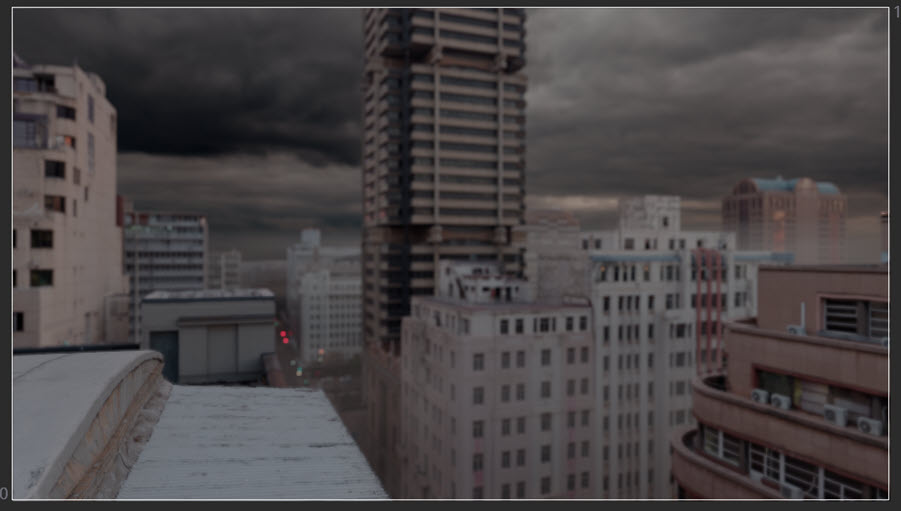
• The Defocus1 node will blur its input, which is the graded camera render. The node will apply the same blur across the whole image, but in this instance, we want the defocus to be depth-based, to emulate a camera's depth of field. Therefore, the depth map node subset is applied as a mask input, so the blurred effect of Defocus1 will only be applied to the areas determined by the mask.
Note: Masks are black and white, and the gradient between black and white is used as a key to determine where and to what extent the mask is visible. White is where the effect is visible, whereas black is where the effect is not visible.
The depth map mask (ViewDepth) being used as the mask:
Defocus without the depth-based mask input
Defocus with the depth-based mask input
• The Colour_Correct1 node can be used for grade-based control on your defocused image.
Section 4
• The Depth_of_Field node drives a defocus effect using the camera depth-based information by reading the camera parameters provided by Camera_Reference1. This means the node will take into a account shape of geometry and image information when creating the effect.
Switch node
The Switch node is a node that enables you to switch between different node subsets. You can create multiple inputs for the Switch node, and then attach the switch node to the Camera_Override node. Only the node subset you select to be the output will display on the wall.
Note: The index of the Which parameter, which defines the output of the node, starts at 0.
In this example, you can switch between the output of the Camera_Reference node without any additional effects, and the two defocus options outlined in sections 3 and 4.
The Camera_Override1 node then displays the final output of these effects over the camera render defined in the Override target property.
Outer Cam
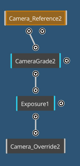
The Outer Cam node set enables you to adjust color and exposure controls for your OuterCam. This can be helpful if you want to make grading adjustments to the outer camera to ensure the environment lighting and coloring stays consistent on set.
• Camera_Reference2 is the image that is being rendered by the OuterCam camera.
• CameraGrade2 and Exposure1 are two color nodes that enable grade-based control on the OuterCam image.
Tip: You want to make sure that the values of CameraGrade1 in the Inner Cam node set and CameraGrade2 in the Outer Cam node set match, so that the color information across the scene is consistent. This is important to make sure the lighting on the actors and the set is cohesive.
• The Camera_Override2 node then displays the final output of these effects over the camera render defined in the Override target property.