Modifying Object Shapes
Many nodes under the Modify menu let you modify the shape of an object as a whole. Modifying only selected portions of an object is also supported using the EditGeo node.
You can modify 3D objects by selecting vertices or faces in the Viewer using the EditGeo node or by using lookup curves, power functions, images, a Perlin noise function, a distortion function, or trilinear interpolation.
Modifying Objects Using the EditGeo Node
EditGeo allows you to directly modify an object’s vertices or faces, depending on the Viewer selection mode currently active. You can also modify multiple objects simultaneously if the EditGeo is downstream of a MergeGeo node with multiple geometry inputs.
Tip: See 3D Selection Tools for more information on selecting objects in the Viewer.
To Modify Objects Using EditGeo
| 1. | Select the 3D object or MergeGeo you want to modify in the Node Graph. |
| 2. | Navigate to 3D > Modify > EditGeo to insert an EditGeo node. |
| 3. | In the node’s controls, use the display dropdown menu to select how you want to view your object in the Viewer while making changes to it. |
Tip: If you don’t have an image or texture associated with your geometry, you may find that enabling the headlamp control in the Viewer properties improves visibility.
Press S in the Viewer to display the Viewer properties, then enable the 3D > headlamp checkbox.
| 4. | Set the Viewer selection mode using the 3D selection tools in the top right corner of the Viewer: |
• Vertex selection - allows you to select individual vertices on geometry, giving you fine control while editing. You can also marquee select multiple vertices or use additive selection by holding down Shift.
• Face selection - allows you to select individual faces on geometry. You can also marquee select multiple faces or use additive selection by holding down Shift.
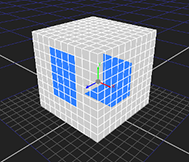
Note: You can turn off occlusion testing by clicking the disable icon ![]() in the Viewer to allow you to select vertices and faces that are hidden from the view point.
in the Viewer to allow you to select vertices and faces that are hidden from the view point.
For example, selecting faces on the “front” of a cube with occlusion testing disabled also selects faces on the opposite, hidden side of the cube.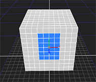
See 3D Selection Tools for more information.
| 5. | Set how the axis handles are aligned with your selection using the axisalignment dropdown: |
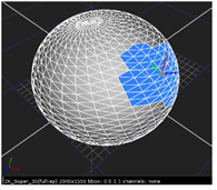
• object - the position of the xyz axis is determined by the average position of all vertices in the selection. The orientation of the axis is the same as the object's orientation.
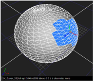
• average normal - the position of the xyz axis is determined by the average position of all vertices in the selection. The orientation of the axis is aligned to the average of the current selection's normals.
In this mode, the z axis always points directly away from the current selection.
|
|
|
| Object alignment | Average normal alignment |
Tip: Holding Ctrl/Cmd+Alt allows you to drag the center of the axis across the surface of the geometry, with the orientation set to the nearest face's normal.
| 6. | Make vertex or face selections in the Viewer as required. Hold Shift to add to a selection or Alt+Shift to remove selections. |
| 7. | When you’re satisfied with your selections, drag the axis associated with the selection to a new position to edit the geometry. |
Tip: You can create smoother, more organic edits using Nuke's soft selection tool ![]() above the Viewer. See Soft Selection for more information.
above the Viewer. See Soft Selection for more information.
To Animate Edits
| 1. | Set the Viewer selection mode using the 3D selection tools in the top right corner of the Viewer: |
• Vertex selection - allows you to select individual vertices on geometry, giving you fine control while editing. You can also marquee select multiple vertices or use additive selection by holding down Shift.
• Face selection - allows you to select individual faces on geometry. You can also marquee select multiple faces or use additive selection by holding down Shift.
| 2. | Make selections in the Viewer and then click |
| 3. | Scrub the playhead to the required frame and transform the geometry using the handles in the Viewer. |
A keyframe is added automatically on the new frame.
| 4. | Repeat the process to produce the required animation. |
Tip: Click ![]() to remove a keyframe at the current frame.
to remove a keyframe at the current frame.
| 5. | Click reset geometry to return the vertices to their original positions. |