Merging Images
With Nuke, you can merge images in a wide variety of ways. In these pages, we teach you how to use the Merge, ContactSheet, and CopyRectangle nodes.
Layering Images Together with the Merge Node
The Merge node with its compositing algorithms allows you to control just how your images are combined.
Note: When using most of the available merge algorithms, Nuke expects premultiplied input images. However, with the matte operation you should use unpremultiplied images.
To Layer Images with the Merge Node
| 1. | Select Merge > Merge (or press M on the Node Graph) to insert a Merge node after the images you want to layer together. |
| 2. | Connect your images to the Merge node’s A and B inputs. |
| 3. | If necessary, you can connect multiple A images to the Merge node. Once you have got the A and B inputs connected as instructed in step 2, drag more connectors from the left side of the Merge node to the images you want to use as additional A inputs. |
Each input is merged in the order connected, for example A3, A2, A1, B.
| 4. | Connect a Viewer to the output of the Merge node so you can see the effect of your merge operation. |
| 5. | In the Merge node’s controls, select how you want to layer the images together from the operation dropdown menu. The default and the most common operation is over, which layers input A over input B according to the alpha of input A. For descriptions of all the available operations, see Merge Operations. |
| 6. | Set which input's bounding box you want to use for the Merge output: |
• union - resize the output bbox to fit both input bboxes completely.
• intersection - use only those parts of the image where the input bboxes overlap.
• A or B - use the selected input's bbox for the output.
See Adjusting the Bounding Box for more information on bounding boxes.
Tip: You can enable a warning to indicate when the bounding box is greater that the format in Nuke's Preferences. See Bounding Box Warnings for more information.
| 7. | Select which input's metadata and frame range is passed down the tree using the metadata from and range from dropdowns. |
| 8. | Using the A channels and B channels dropdown menus, select which channels to use from the A and B inputs and which channels to use as the A and B alpha. If you want to merge more channels than these and output them into the same channels, select them from the also merge dropdown menus and checkboxes. |
| 9. | From the output dropdown menu, select the channels you want to write the merge of the A and B channels to. Channels named in the also merge dropdown menu are written to the same output channels. |
| 10. | If necessary, you can also adjust the following controls: |
• To select which input’s metadata to pass down the tree, use the metadata from dropdown menu.
Note: When metadata from is set to All and there are keys with the same name in both inputs, keys in B override keys in A.
For more information on file metadata, see Working with File Metadata.
• To dissolve between the original input B image (at 0) and the full Merge effect (at 1), adjust the mix slider. A small light gray square appears on the node in the node graph to indicate that the full effect is not used.
• If you want to mask the effect of the Merge operation, select the mask channel from the mask dropdown menus. To invert the mask, check invert. To only apply the effect at the edges of the mask, check fringe.
Note that you should not use the alpha of the inputs for the mask. It produces erroneous results (though the error is often hard to see); you can achieve better results by turning on alpha masking.
• From the Set BBox to dropdown menu, select how you want to output the bounding box. The default is union, which combines the two bounding boxes. You can also select intersection to set the bounding box to the area where the two bounding boxes overlap, A to use the bounding box from input A, or B to use the bounding box from input B.
• By default, Nuke assumes that images are in linear color space. However, if you want to convert colors to the default 8-bit color space defined in the LUT tab of your project settings (usually, sRGB), check Video colorspace. The conversion is done before the images are composited together, and the results are converted back to linear afterwards. Any other channels than the red, green, and blue are merged without conversion.
Checking this option can be useful if you want to duplicate the results you obtained from an application that uses the standard compositing math but applies it to non-linear images (for example, Adobe® Photoshop®). In this case, you typically also need to make sure premultiplied is not checked in your Read node controls.
• By default, the same math is applied to the alpha channel as the other channels. However, according to the PDF/SVG specification, many of the merge operations (for example, overlay and hard-light) should set the alpha to (a+b - ab). This way, the input images remain unchanged in the areas where the other image has zero alpha. If you want to enable this, check alpha masking.
Bounding Box Warnings
Zooming into the Viewer to work on a shot means that you can't always see the extent of the bounding box in relation to the format, which can result in unnecessary processing.
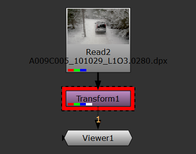
To make it easier to see the state of your bounding box, Nuke can display visual warnings on the nodes that affect the bounding box. To enable the warnings, in Nuke's Preferences under Panels > Node Graph, enable Bounding Box Warning:
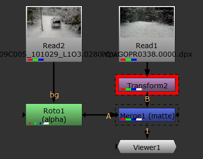
• red rectangle with dotted stroke - the indicated node creates a bounding box greater than the format.
• dotted stroke without the red rectangle - the bounding box size is greater than the format at the indicated node, but the bounding box size has been set by an upstream node.
The bbox warning threshold controls how far past the edge of the format the bounding box can expand before the warning is displayed in the Node Graph. For example, if you're working with UHD_4K footage and the default 10% threshold, you can expand the bounding box horizontally by 384 pixels before the warning is displayed.
Tip: You can set the color of the warning rectangle in the Preferences under Panels > Node Graph > Bounding Box Warning.