Rotoscoping to Correct Errors in the Source
Viewing the main preview from C_CameraSolver allows you to pick out areas of the solve that can be quickly cleaned up by editing the alpha masks in the source, before stitching the results. You'll still need to paint out objects that you don't want in the shot, such as the rig, but this workflow can cut down the amount of work required later on.
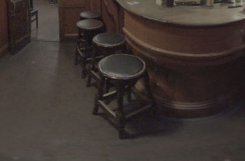
Examine the main preview to find areas that are bleeding from one camera view to another. The example shows part of a stool bleeding into overlap regions.
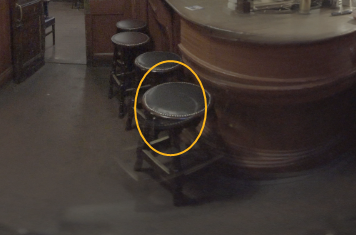
| 1. | The first step is to look through the views to determine where the source is located. Turn on the C_CameraSolver overlay to display the cameras and overlap regions and then click the views above the view to pick the cameras. |
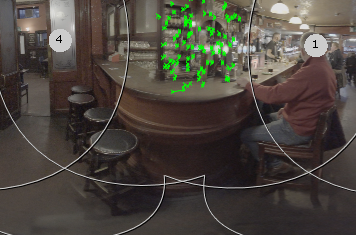
In this example, cameras 1 and 4 contain the source.
| 2. | Next, split out the views so that you can work on the individual shots. Select the C_CameraSolver in the Node Graph, press Tab to display the node selector, and then add a Split and Join. |
Tip: If you only need certain views split out, you can use the Split and Join Selectively node instead. See Split and Join Selectively for more information.
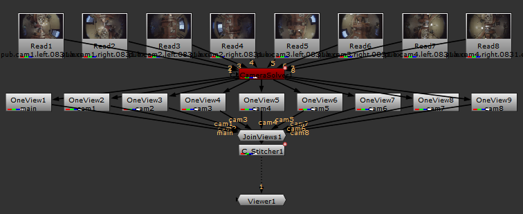
This is a vanilla Nuke operation, which adds a OneView node for each view present upstream, and then connects them together again using a JoinViews node.
Note: You can paint in latlong space as well by adding the Split and Join after C_Stitcher, but remember to add a C_Blender after the join so that the views are recombined into a single stream. See Blending Multiple Views Together for more information.
| 3. | Connect the Viewer to the OneView node containing the output from the camera you're interested in and display the alpha as a Mat by pressing M over the Viewer. This overlays the alpha mask created by the solve. |
| 4. | Add a Roto node to the script and draw a bezier around the area of the shot you don't want. |
Tip: It's a good idea to feather the roto shape to produce a better result. You can do this by selecting a point on the shape and pressing E a few times. See Using RotoPaint for more information.
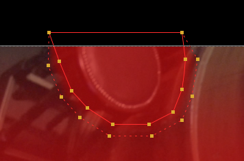
| 5. | In the Roto node's Properties panel, click the color wheel icon in the shapes list, and set the bezier color to black, or zero alpha. |
The bezier shape now trims the alpha mask created by C_CameraSolver so that it doesn't include the area containing the object.
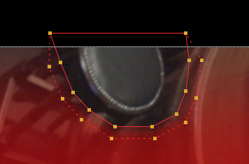
| 6. | Connect the Viewer to the C_Stitcher node and disable and enable the Roto node to view the results. |
|
|
|
