Object Material Properties
The nodes under the Shader menu let you define the material attributes of geometric objects in a scene, including the quality of light reflected back to the camera from an object’s surface. Using these nodes, you can control what material your objects seem to be made of.
You can also add several Shader nodes one after the other to produce more complex effects. For this, you should use the unlabeled inputs on the Shader nodes.
The material property settings you apply affect the render output of the scene.
You can insert 3D shader nodes in the following places in your scripts:
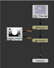
• between the 2D image you’re using for the surface texture and the 3D object node that creates the surface, or
• after the 3D object nodes using the ApplyMaterial node. This is a good way to apply a global material to all objects. See Applying a Material Using the ApplyMaterial Node.
You can use the map connectors to input a mask image to limit the effect of the material change.
|
|
| Diffuse and Specular nodes. |
Note: You can only see the effect of your changes to an object’s material properties in the 2D view.
Applying a Material Using the ApplyMaterial Node
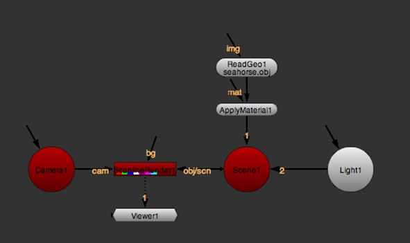
The ApplyMaterial node applies a material from the mat input to your 3D object(s).
| 1. | Select 3D > Shader > ApplyMaterial to insert an ApplyMaterial node into your script. |
| 2. | Connect the unnamed input of the ApplyMaterial node to your geometry (for example, a Sphere, ReadGeo, or ModelBuilder node). |
Tip: If you want to apply a global material to several objects, you can also connect the unnamed input to a MergeGeo node. This overrides any materials applied to the individual geometry nodes before they were merged.
| 3. | Connect your materials (for example, a 2D texture image, a BasicMaterial node, or a Wireframe node) to the ApplyMaterial node’s mat input. |
By default, ApplyMaterial applies the material from the mat input onto all incoming geometry objects.
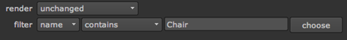
| 4. | If you created your geometry using ModelBuilder or imported an Alembic file using ReadGeo, you can choose to only apply the material onto a particular object in the incoming geometry. To do so, open the ApplyMaterial properties and set filter to name. This allows you to tell ApplyMaterial to ignore any geometry that doesn't match the filter on the right. |
Note: You can also limit a material to a particular object if your geometry was created or imported using a third-party plug-in that adds a name attribute for the geometry objects.
| 5. | To set how to filter the incoming geometry objects, set the dropdown menu next to name to: |
• equals - set the material on any objects whose name matches the string in the filter name field exactly.
• doesn't equal - set the material on any objects whose name does not match the string in the filter name field exactly.
• contains - set the material for any objects whose name contains the string in the filter name field.
This can be useful when you have some structure to your object names. For example, if you have objects like /Root/Chair/Seat, /Root/Chair/Back, and /Root/Table, you can select contains and set the filter name field to Chair to apply the material to all parts of the chair while leaving the table alone.
• doesn't contain - set the material for any objects whose name does not contain the string in the filter name field.
| 6. | To set the filter name, type the name directly into the text entry field or use the choose button to open the Object Name Chooser dialog and select a filter name from a list of incoming geometry objects. |
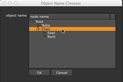
Tip: You can also Ctrl/Cmd+click or Shift+click in the Object Name Chooser dialog to select multiple objects.
Adjusting the Diffuse Color
The Diffuse node lets you adjust the color of the material when illuminated. The material appears darker as the surface points away from the light, as the light is not falling on it.
| 1. | Select 3D > Shader > Diffuse to insert a Diffuse node into your script. |
| 2. | Place the Diffuse node between your 2D texture image and your 3D object node, or connect it to an ApplyMaterial node’s mat input. |
| 3. | In the Diffuse properties, use the channels dropdown menu to select the channels you wish to process. |
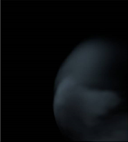
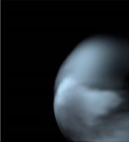
| 4. | Adjust the white slider to control the diffuse color. By default, this is in grayscale, but you can also adjust the individual r, g, and b values. The higher the value, the brighter the material. |
|
|
|
|
Diffuse: Low white value. |
Diffuse: High white value. |
Adjusting Specular Highlights
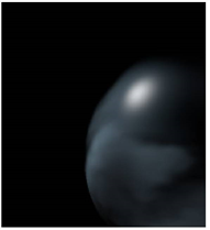
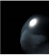
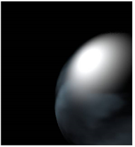
You can use the Specular node to control how bright and wide the highlights on the material seem. The location of the viewpoint is significant: the specular highlights are the brightest along the direct angle of reflection.
| 1. | Select 3D > Shader > Specular to insert a Specular node into your script. |
| 2. | Place the Specular node between your 2D texture image and your 3D object node, or connect it to an ApplyMaterial node’s mat input. |
| 3. | In the Specular properties, use the channels dropdown menu to select the channels you wish to process. |
| 4. | Adjust the white slider to control the brightness of the specular highlight. The higher the value, the shinier the material seems. |
|
|
|
|
Low white value. |
High white value. |
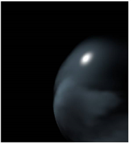
| 5. | To control the width of the highlights, adjust the min shininess and max shininess sliders. |
|
|
|
|
Low shininess value. |
High shininess value. |
| 6. | If necessary, adjust shininess channel to control how the input channels are used to map the black and white values to the min shininess and max shininess parameters when a mapSh input is connected. Select red to use the red channel for the mapping, green to use the green channel, blue to use the blue channel, luminance to use the luminance, or average rgb to use the average of the red, green, and blue channels. |
Simulating Materials That Emit Light
You can use the Emission node to simulate lamps or other sources that emit light.
| 1. | Select 3D > Shader > Emission to insert an Emission node into your script. |
| 2. | In the Emission properties, use the channels dropdown menu to select the channels you wish to process. |
| 3. | Adjust the emission slider to change the brightness of non-illuminated areas for the surface. |
The higher the value, the more light the material seems to emit and the brighter it appears.
Adjusting Diffuse, Specular, and Emission Using a Single Node
The BasicMaterial node is a combination of the Diffuse, Specular, and Emission nodes, allowing you to control all three aspects of the material from a single properties panel.
| 1. | Select 3D > Shader > BasicMaterial to insert a BasicMaterial node into your script. |
| 2. | Place the BasicMaterial node between your 2D texture image and your 3D object node, or connect it to an ApplyMaterial node’s mat input. |
| 3. | The BasicMaterial node has several map inputs you can use to mask the effect of the node. Use: |
• mapD to modulate the diffuse component,
• mapS to modulate the specular component,
• mapE to modulate the emission component, and
• mapSh to modulate the shininess value.
| 4. | In the BasicMaterial properties, use the channels dropdown menu to select the channels you wish to process. |
| 5. | Adjust emission to change the color of the light the material emits. Note that when you have an image connected to the unlabeled input of the BasicMaterial node and adjust this value, you need to look at the rendered 2D image to see the effect of your changes. Changing the emission value does not have any effect in the 3D Viewer. |
| 6. | Adjust diffuse to control the color of the material when illuminated. |
| 7. | Use specular to control how bright the highlights on the material seem. |
| 8. | Adjust min shininess and max shininess to set the minimum and maximum shininess values. If you haven’t connected an image to the mapSh input of the node, the average of these values is used as the shininess value for the material. |
| 9. | Select a shininess channel to control how the input channels are used to map the black and white values to the minShininess and maxShininess parameters when a mapSh input is connected. Select red to use the red channel for the mapping, green to use the green channel, blue to use the blue channel, luminance to use the luminance, or average rgb to use the average of the red, green, and blue channels. |
Simulating Smooth, Regular Surfaces
The Phong node uses the Phong algorithm to smooth edges between faces. It provides realistic shading and highlights for smooth materials, such as skin and other organic surfaces.
| 1. | Select 3D > Shader > Phong to insert a Phong node into your script. |
| 2. | Place the Phong node between your 2D texture image and your 3D object node, or connect it to an ApplyMaterial node’s mat input. |
| 3. | The Phong node has several map inputs you can use to mask the effect of the node. Use: |
• mapD to modulate the diffuse component,
• mapS to modulate the specular component,
• mapE to modulate the emission component, and
• mapSh to modulate the shininess value.
| 4. | In the Phong properties, use the channels dropdown menu to select the channels you wish to process. |
| 5. | Adjust color to change the material color. |
| 6. | Adjust emission change the color of the light the material emits. |
| 7. | To control the color of the material when illuminated, adjust diffuse. |
| 8. | To control how bright the highlights on the material seem, adjust specular. |
| 9. | To control how shiny the material appears, adjust shininess. |
| 10. | To set the minimum and maximum shininess values, adjust min shininess and max shininess. If you haven’t connected an image to the mapSh input of the node, the average of these values is used as the shininess value for the material. |
| 11. | Select a shininess channel to control how the input channels are used to map the black and white values to the minShininess and maxShininess parameters when a mapSh input is connected. Select red to use the red channel for the mapping, green to use the green channel, blue to use the blue channel, luminance to use the luminance, or average rgb to use the average of the red, green, and blue channels. |
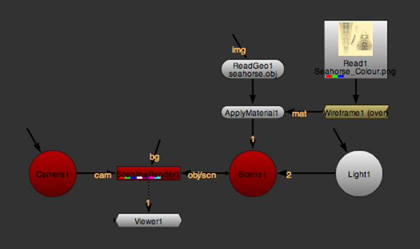
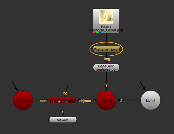
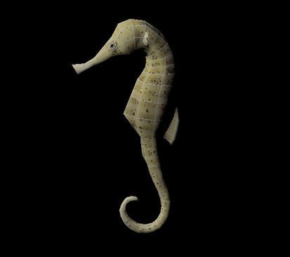
Rendering a Wireframe Overlay on Your Geometry
The Wireframe node allows you to render a wireframe overlay on the surface of your geometry object or particle simulation. This can be useful, for example, if you want to:
• check that your texture projection correctly lines up with your geometry.
• create a quick render of your 3D scene to check the positioning of objects.
• create motion graphics.
• create "making of" videos.
Note: The Wireframe node currently only works if you are rendering your 3D scene using ScanlineRender, RayRender and PrmanRender do not support the Wireframe shader.
| 1. | Select 3D > Shader > Wireframe to insert a Wireframe node into your script. |
| 2. | Place the Wireframe node between your 2D texture image and your 3D object node, or connect it to an ApplyMaterial node’s mat input. |

| 3. | In the Wireframe properties, use the channels dropdown menu to select the channels you wish to process. |
| 4. | From the operation dropdown, select how to apply the wireframe overlay to your geometry: |
• opaque - display the wireframe on fully opaque black input geometry.
• see through - display the wireframe on fully transparent geometry.
• over - display the wireframe on top of the input shader or texture.
• multiply - multiply the wireframe by the input shader or texture and display it on fully transparent geometry.
• modulate - apply standard diffuse shading to the wireframe and display it on top of the input shader or texture. This takes into account any lights in the scene.
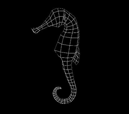
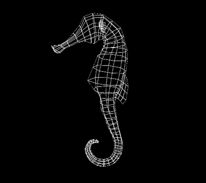
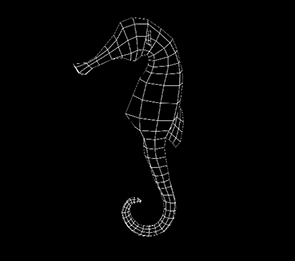
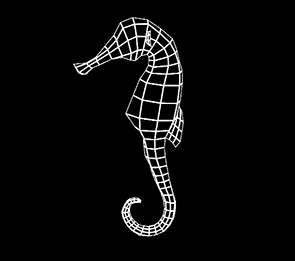
| 5. | To set the width of the wireframe lines (in pixels), adjust line width. |
|
|
|
Line width set to 0.5. |
Line width set to 3. |
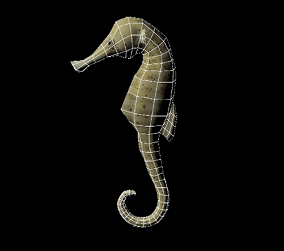
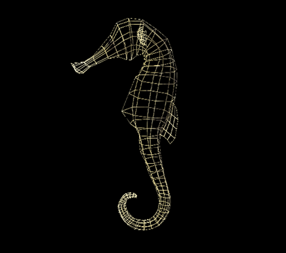
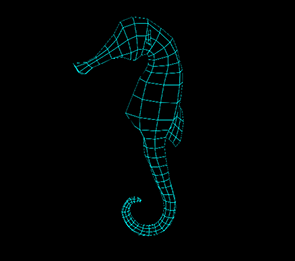
| 6. | To set the color and transparency of the wireframe lines, adjust line color. |
|
|
|
|
Line color set to white. |
Line color set to cyan. |