Placing an Image on the Planar Surface
When you’ve tracked a planar surface on your footage, you might want to place an image on it. To place an image on the tracked planar surface, do the following:
|
1.
|
Ensure you’re on the reference frame you’ve drawn the roto shape on, and select the PlanarTrackLayer you want to use in the Create New Track dropdown on top of the Viewer. |

|
2.
|
Check show plane  and correct plane and correct plane  on the properties panel to make your planar surface visible and to enable modifying it. You can also click the corresponding buttons above the Viewer. on the properties panel to make your planar surface visible and to enable modifying it. You can also click the corresponding buttons above the Viewer. |
|
3.
|
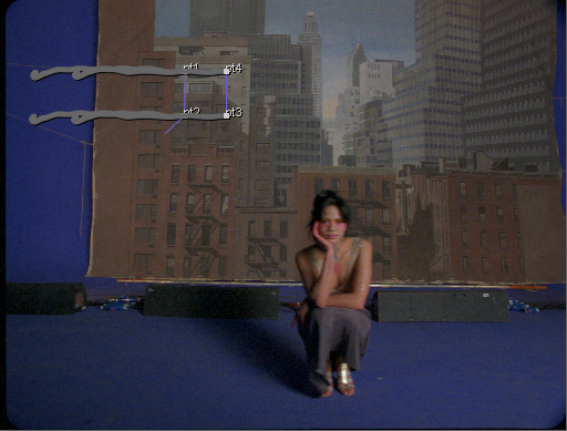
A rectangle indicates your planar surface in the Viewer. If the rectangle is very large, you can click the Resize Planar Surface to Image button  in the Viewer. in the Viewer. |
|
4.
|
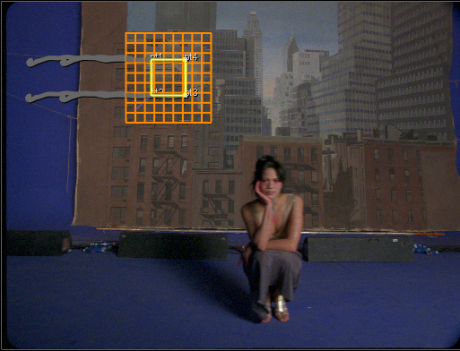
Drag the corners of the rectangle to cover the area over which you want to place an image. Click the Show grid lines button  in the Viewer to use a guide grid in positioning your rectangle. in the Viewer to use a guide grid in positioning your rectangle. |

This shows grid lines corresponding with the current plane and it helps with realigning your plane.
|
5.
|
Scrub in the timeline to make sure the planar surface sticks to the area you want. |

If you need to adjust it, you can do one of the following:
• Adjust the points in the reference frame to change the planar surface over the whole footage. This way you’re adjusting the actual dimensions of the planar surface rectangle. The rectangle appears in yellow.
• Adjust the points in other frames to change the planar surface in the current frame and its adjacent frames. This way you’re correcting small drifts in the planar surface rectangle without changing its real dimensions. The rectangle appears in blue.
|
6.
|
The values in the CornerPin points show how your plane has warped from the reference frame to the current frame. Adjust them in the Curve Editor by the selecting Curve Editor tab above the Node Graph. |
Note: While you can drag the CornerPin points data to another node or control by simply dragging selecting all the points and dragging on any of the animation buttons. If you press Ctrl/Cmd+drag, this creates an expression link to the CornerPin points data instead of placing them in the new location.
|
7.
|
Read in the image you want to place on the tracker planar surface. |
|
8.
|
To convert the new image to the same format, insert a Reformat node and select the correct image format from the output format dropdown. |
|
9.
|
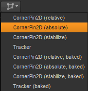
You can now add a CornerPin node to help you place an image on the plane. Click the Create CornerPin2D Node dropdown in the Viewer (or use the Export dropdown in the properties panel) and select the type of corner pinning you want to use. |

See the 'Tracker Menu Options in the Viewer' section in Tracking a Plane for more information about the different types of CornerPin.
|
10.
|
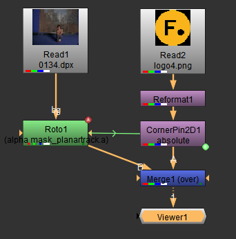
Insert a Merge node and connect the CornerPin node to the A input, and the Roto node to the B input. Your node tree should now look similar the one shown below: |

|
11.
|
You can now make any other required changes to your image. For example, you can adjust the mix control in the Merge node's properties, to change the opacity of the image. |
|
12.
|
When you're happy, close all the node property panels to see the result clearly in the Viewer. You can scrub through the timeline and make sure the position of the image in sorrect throughout. |
![]()
![]()
![]()
![]()
![]()
