New 3D Scenes in the Scene Graph
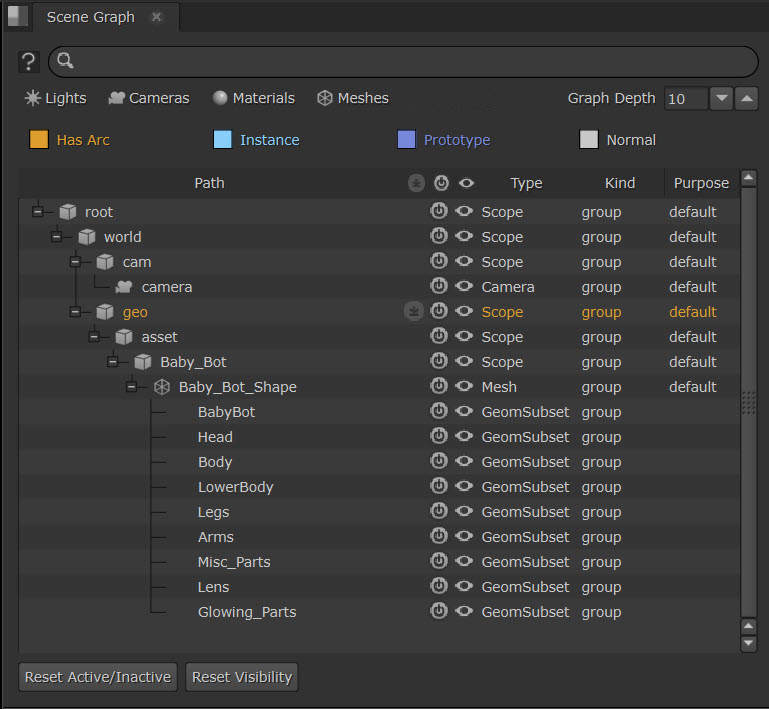
The Scene Graph offers an overview of the scene, and is a tool to view, navigate and manage large 3D scenes, allowing artists to work with more flexibility. Essentially, the Scene Graph is a list of everything within the 3D stage at the point where the Viewer is connected. Selecting entries in the Scene Graph highlights the associated objects in the Viewer.
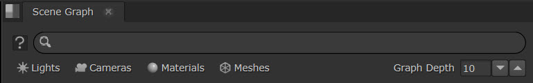
Accessing the Scene Graph
In the menu select Workspace > 3D to open 3D workspace where the Scene Graph will appear. Or go to  > Windows> Scene Graph to open it directly.
Scene Graph Features
Hierarchical Structure
The Scene Graph uses a hierarchical representation of the USD stage, in contrast to Nuke’s classic flat structure. This hierarchy covers prims such as geometry, lights, cameras, and materials, each with a unique ID or path, promoting a well-organized structure. The Scene Graph is a list of everything within the 3D stage at the point where the Viewer is connected.
The Scene Graph has styling to help you visualize the hierarchy of your stage. Prims with Arcs, Instances and Protypes appear in different colors:

Geometry Highlight and Selection Synchronization
Synchronization between the Scene Graph and the viewer enables easy selection and navigation. Selecting an item in the Scene Graph highlights the respective item in the viewer and vice versa.
Searching and Filtering in the Scene Graph
Searching
A search bar at the top of the Scene Graph lets you swiftly locate items in the scene, highlighting the search results in bold. Cycle through the results by repeatedly pressing the Enter key, or pressing Shift + Enter to cycle back.
Matches highlight in bold. The number of the selected results and the total number of search results are shown to the right of the search bar.
Filtering
There are a variety of preset filters which you can enable using the buttons just below the search bar - these show all Lights, Cameras, Materials, and Meshes. You can toggle them on and off, and use multiple at once.
For example, Cameras filter is applied to this stage. Other types of prims are grayed out.
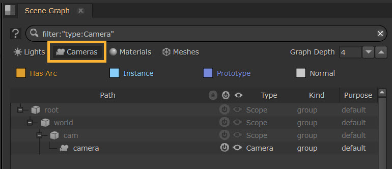
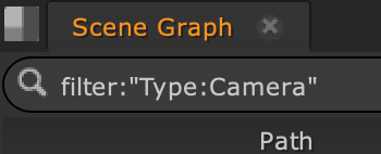
You can also apply filters by typing the syntax in the Scene Graph search bar. For example, for filtering by Type for Cameras, the syntax would be:
Filter:“Type:Camera”
Columns in the Scene Graph
The Scene Graph panel contains various columns representing different data facets. These include:
-
Path: Displays the hierarchical structure of objects.
-
 (Payload): A USD specific concept to control memory usage by deciding the parts of a scene to load.
-
 (Active): Allows the activation and deactivation of specific prims.
-
 (Visibility): Offers control over the visibility of 3D objects in the viewer.
-
Type: The data category of an element. For example, mesh represents meshes, and a float attribute stores numerical values.
-
Kind: The organizational role of an element in the hierarchy. It is categorized as values like component for individual objects or assembly for a collection of components.
-
Purpose: Categorizes components or primitives based on their role in different stages of the production pipeline. For example, An object with a render purpose would be included in the final rendering pass . A default purpose generally means that it is a primary element of the scene. It should be taken into account in various processes, such as rendering, simulation, and interaction within the viewport.
Payload Management
Payloads let you choose which parts of a scene are loaded into memory. This helps you save on memory and speed up load times, which can be particularly useful for complex scenes with high levels of detail.
If you’re using payloads, you can load individual items by clicking on the icon corresponding to each item in the payload column. Payloads are loaded by default, which is indicated by the light gray icon . The icon will switch to a dark gray icon  when the payload is unloaded.
Prim Visibility and Active Status
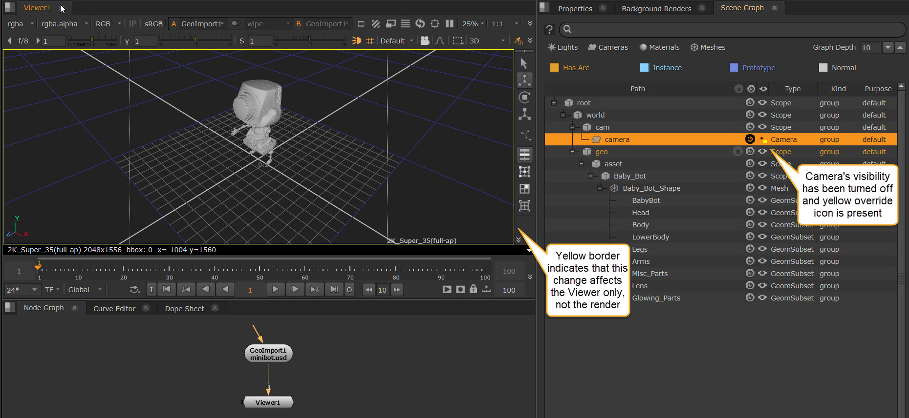
You can turn prims off (deactivate them) in the Scene Graph or simply not show them in the Viewer. Changing a prim’s Visibility or Active overrides in the Scene Graph will only affect those states for the Viewer, not for any upstream nodes, e.g. Scanline Render nodes or Write nodes.
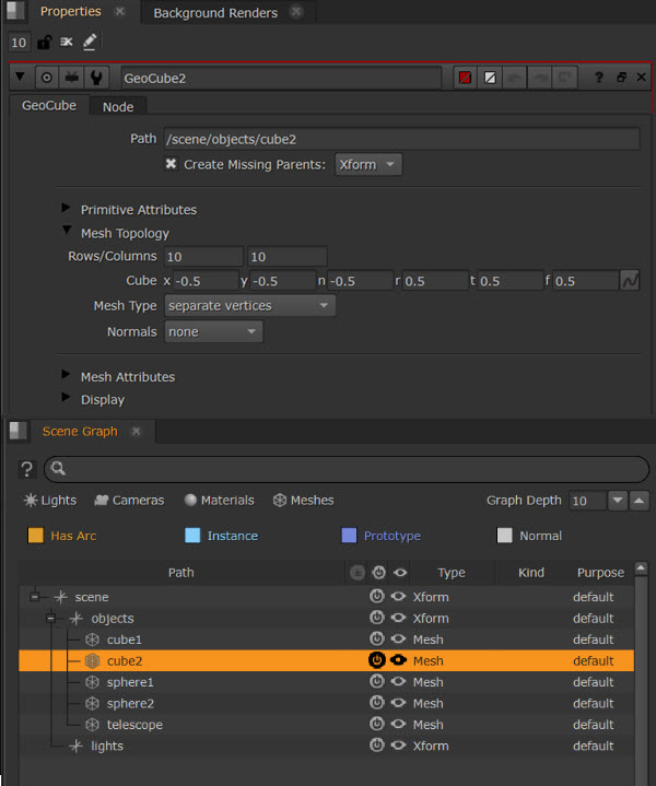
An ‘on’ icon ![]() in the Active column indicates that the prim is active. You can toggle between the ‘on’ icon and a dot to choose if the prim is active or deactivated. When deactivated, whilst the slot for the prim is still technically in the Scene Graph, the prim is effectively removed from the stage. Children of a deactivated prim will not be shown in the scene graph.
in the Active column indicates that the prim is active. You can toggle between the ‘on’ icon and a dot to choose if the prim is active or deactivated. When deactivated, whilst the slot for the prim is still technically in the Scene Graph, the prim is effectively removed from the stage. Children of a deactivated prim will not be shown in the scene graph.
An eye icon ![]() in the Visibility column indicates that the prim is visible in the viewer. Toggle the eye to show/hide the prim. Unlike deactivation, the Scene Graph is not affected, only the Viewer.
in the Visibility column indicates that the prim is visible in the viewer. Toggle the eye to show/hide the prim. Unlike deactivation, the Scene Graph is not affected, only the Viewer.
Note: Any changes to the prim Active and Visibility state which affects the Viewer only is signalled by a yellow border around the edge of the Viewer.
Right-click on a prim and use the context menu to Show or Hide the visibility of the prim.
Overrides: Indicators and Management
A small yellow dot on a visibility or active icon indicates that this control for the prim has been overridden, in other words it has changed from the state it was in when imported.
If you no longer require the overrides and their indicators, you can use the right-click context menu and select Clear overrides. All yellow dots then disappear to indicate that these are no longer overridden.
The Clear overrides option is not context specific and always applies to the whole scene graph.
Tree Operations
Expand and Collapse: Use the plus and minus icons next to the prim name to expand or collapse the scene structure. Hold Shift when expanding to also expand all nested elements within a parent.
Multi-Selection: Select multiple items using Shift to select a range or Control to multi-select individual prims.
You can also use the right-click context menu on a prim to choose Collapse all or Expand all.
Using Masks and Paths in the Scene Graph
Path and Mask knobs on certain 3D nodes can be used to place items in the Scene Graph hierarchy. Path knobs are located on creation nodes like GeoCube, allowing you to specify the desired position in the scene's hierarchy.
Modifier nodes such as GeoTransform have a Mask knob, to define the prims in the scene that you want the node to affect.
Note: For more information see Using Paths and Masks.
The Mask knob is a dropdown with the most common mask actions displayed, such as All Cameras and All Lights, to make it easier to select the most appropriate mask for your needs. The default is All roots or All meshes, depending on the node, which selects the top most level Xforms in your scene graph.
You can also set Mask knobs by:
Using the Scene Graph picker  |
Copying the prim paths from the prims you currently have selected  |
Select prims in the Viewer using the eyedropper tool  |
| Drag and drop from the scene graph onto the knob |
| Type into the path(s) directly |
The Scene Graph picker button next to the Mask knob opens a pop-up scene graph, showing the hierarchical scene at that point in the node graph. The pop-up shows the scene's hierarchy from the node and everything upstream.
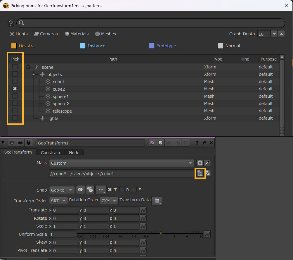
Use the Pick column to select items.
Making Selections
Make your selections using the checkbox in the left Pick column, or double-click on a prim to check the box automatically. Press OK to confirm the selection.
The selection(s) are input into the mask knob. You can select individual or multiple prims using common multi-select hotkey modifiers such as Shift+click.
Some nodes require a single selection, such as in the import prim path knob on Camera nodes. In this case, the pop-up scene graph will offer a single selection only. Double-click the chosen camera, to select it as input to the mask knob, which closes the pop-up scene graph automatically.
Tip: The pop-up scene graph uses the same search feature and filtering system as the main scene graph. Filters are automatically applied on certain nodes. For example, when choosing a prim path for a Camera node, only Cameras will be filtered, and only a single selection is available.