Warping
Warping refers to manipulating an image so that elements in the image are distorted. Unlike many of the transformations described under Transforming Elements, warps are transformations that only affect some of the pixels in an image rather than all of them. For example, you might make an animal’s eyes bigger or a person’s smile wider without affecting the rest of their features.
This is not to say that the pixels around the area you are moving do not move with the area. They do, because accommodating the change this way often produces more realistic results. However, the distortion lessens the further you get from the moved pixels. You also have some control over which pixels are moved and which are not, and can isolate the warp to a small area. Still, in an ideal situation, the subject you are going to warp is a subject you can key out or rotoscope to isolate it from its background before you create the warp. This way, you can be sure that the background stays intact.
In addition to performing creative manipulations on the shapes of the subjects in your images, you can also use warping to simulate different types of film or video lenses or to remove unwanted lens distortions.
Below, we discuss how to warp images, first using the GridWarp node and then the SplineWarp node. Finally, we also teach you to animate the warps. Again, we start with the GridWarp node and then show you how to do the same with the SplineWarp node.
Warping Images Using the GridWarp Node
The GridWarp node allows you to warp images by transferring image information from one Bezier grid onto another. When using this node, you first position the source grid, which defines where to warp from. Next, you position the destination grid, which defines where to warp the image to. This grid can be a duplicate of the source grid, or you can define it separately. When you manipulate the destination grid, the corresponding warp is applied to the source image.
The GridWarp node also includes controls for animating the warp and selecting the level of filtering used to remove any artifacts the warp may have caused.
To Warp an Image Using the GridWarp Node
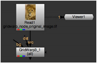
| 1. | Select Transform > GridWarp to insert a GridWarp node after the image you want to warp. |
| 2. | Connect the src input and a Viewer to the image. |
| 3. | When the GridWarp properties panel is open, by default the destination grid overlay appears in the Viewer. You can show or hide the source and destination grids using the |
Note: GridWarp automatically attempts to resize the grids to the image size as long as you have not modified any of the control points.
If the grids are not the same size as the input image, click the Resize to image buttons under both Source Grid and Destination Grid.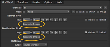
| 4. | Use the Viewer tools to control the following aspects of the grids: |
Note: You can use the copy and paste buttons ![]() in the grid controls to copy control point keyframes between the source and destination grids.
in the grid controls to copy control point keyframes between the source and destination grids.
|
Control |
What it does |
|
output |
Controls the output displayed in the Viewer: • source - the source image and source grid. • sourcewarped - the source image and destination grid. • destination - the destination image and destination grid. • destinationwarped - the destination image and source grid. • morph - the morphed image, controlled by the warp and mix parameters, and both grids. |
|
|
When enabled, the grids shown in the Viewer depends on the output setting. For example, if output is set to source warped, only the destination grid appears in the Viewer. |
|
|
When enabled, the source grid is displayed in the Viewer. This control can be overridden by the |
|
|
When enabled, the destination grid is displayed in the Viewer. This control can be overridden by the |
|
|
When enabled, changes to points in a grid are automatically keyed. You can disable this and set your keyframes manually, which is particularly useful if you intend to use the Curve Editor. See Animating Warps. |
|
ripple |
Rippling keyframes allows you to adjust the position of a stroke/shape point on one frame and have that same relative adjustment applied to the point across all frames or a specified range of frames. • off - ripple edit is disabled. • all - ripple all frames in the sequence. • from start - ripple frames from the first frame to the current frame. • to end - ripple frames from current frame to the last frame. • range - ripple all frames within the from and to fields. |
|
label points |
When enabled, points selected on the grid are labeled x,y measured from the origin. |
|
|
When enabled, the transform handle overlays all selected points. |
|
|
When enabled, a low resolution preview displays when points are moved on a grid. Once the render is complete, the low-res image is updated. |
|
divisions |
Enter the number of divisions required in the field to modify the grid. The number of divisions must be between 3 and 20. You can also click and hold the slider to overlay a preview of the subdivisions. GridWarp attempts to modify the grid based on the current control point distribution. Note: When using the preview, accuracy may suffer at lower divisions and additional smoothing may be required at higher divisions. |
|
|
Click to enable Edit mode. Select individual points, multiple points using shift-click, or marquee groups of points. Edit mode also allows you to adjust the curve between points to produce distortion. |
|
|
Click to enable Insert mode. Click on a horizontal line to add a vertical line to the grid and vice versa. |
|
|
Click to enable Delete mode. Click on a grid line to remove it from the Viewer. |
|
|
Click to enable Draw Boundary mode. The cursor changes to a crosshair and you can drag a marquee in the Viewer to create a custom grid. |
|
|
Click to subdivide the grid columns across the currently selected area. |
|
|
Click to subdivide the grid rows across the currently selected area. |
|
|
Click to subdivide the grid columns and rows across the currently selected area. |
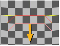
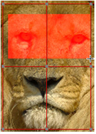
| 5. | Modify the grid around the area you want to warp. Usually, you want the grid to conform to the subject of the source image. For example, if you are warping an animal’s eyes, you need to create grid lines that follow the edges of the eyes. |
Note: If you have both grids visible when you move a point, and the same point for both grids are on top of each other, both points are moved and you won’t see any distortion.
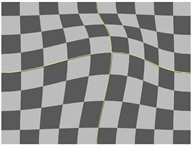
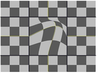
You can use the grid lines to isolate the areas you do not want to warp. You do this by adding grid lines between the area you intend to warp and the area you don’t want to change.
|
|
|
| An unlimited warp. | The same warp limited to a small area with grid lines. |
When you select a point, four tangent handles appear around it. You can use these handles to modify the curves connecting the points.
To move several points together, draw a marquee around them and use the transformation overlay that appears.
![]()
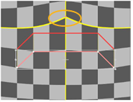
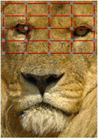
You can also use the Draw Boundary tool in the Viewer to quickly set a user defined grid. Click Draw Boundary and draw a marquee over the required area of the image.
|
|
|
| The Draw Boundary marquee. | The resulting user-defined grid. |
Note: You can also use the Curve Editor to edit curves by right-clicking a control point and selecting Curve Editor > points, tangents, or both.
The curves appear in the Dope Sheet as long as the GridWarp Properties panel is open.
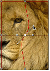
| 6. | In the areas where you want to warp the image, drag the points on the grid to a new position. When you click on a point, the point changes color to indicate whether it’s in focus (green by default) and whether it has an expression set (red by default). You can change the default colors on the Viewers tab in the Preferences. |
The pixels in these areas are moved in the direction you moved the points. Pixels in the nearby areas are also moved to accommodate the change, but the distortion lessens the further you get from the repositioned points. If you don’t want a nearby area distorted, add more grid lines between the area and the points you want to move before you drag the points to a new location.
Tip: You can nudge selected control points by a single pixel using the numeric pad 4 and 6 to nudge left and right, or 8 and 2 to nudge up and down.
Holding down Shift and using the numeric pad moves the selected points by 10 pixels, for example, Shift+6 moves the selected points 10 pixels to the right.
| 7. | To better see what the warped image looks like, press Q on the Viewer to toggle the overlay off. |
To compare the original and warped images, press D on the GridWarp node to disable and enable it. If you see changes in the areas you don’t want to warp, go back to modifying the grid.
| 8. | If necessary, animate the grid to match any movement in the source image. For more information on how to do this, see Animating Warps. |
| 9. | You can adjust the controls described in the following table to enhance your results. |
|
Control |
What it does |
|
GridWarp Tab |
|
|
channel |
Sets the channels affected by the distortion. |
|
mask |
Connect a mask input and set the channel to use as a mask. By default, the mask is limited to the non-black areas of this channel. Use the checkboxes to modify the mask properties: • inject - copies the mask input to the predefined mask.a channel. Injecting the mask allows you to use the same mask further downstream. • invert - inverts the use of the mask channel so that the mask is limited to the non-white areas of the mask. • fringe - only apply the effect at the edges of the mask. |
|
background |
The warped image is rendered on top of an unwarped background. This control sets what to use as that background: • on black - render the warped image on top of a constant black image. • on src - render the warped image on top of the image connected to the src input of the GridWarp node. • on dst - render the warped image on top of the image connected to the dst input of the GridWarp node. • on bg - render the warped image on top of a background image connected to the bg input of the GridWarp node. |
|
background mix |
Blends between the output of the GridWarp node (at 0) and whatever you have selected from the background dropdown menu (at 1). |
|
Set bbox to |
Sets the boundary box properties. |
|
Render Tab |
|
|
submesh |
Sets the number of subdivisions that are created between Bezier curves in the grid. The higher the value, the more accurate the distortion between the grid lines, but rendering time increases. |
|
filter |
Select the appropriate filtering algorithm (see Choosing a Filtering Algorithm). |
|
Options Tab |
|
|
source color |
Sets the source grid color. |
|
destination color |
Sets the destination grid color. |
Warping an Image Using the SplineWarp Node
The SplineWarp node deforms an image based on multiple Bezier or B-spline curves that you create. Source curves define where to warp from, while destination curves define where to warp the source image to. Unlike the GridWarp node, you can draw these curves anywhere on the image, rather than only adding points on the existing grid lines, then join them to create the source and destination. The controls for adding and modifying points are similar to the RotoPaint node controls.
To Warp an Image Using the SplineWarp Node
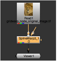
| 1. | Select Transform > SplineWarp to insert a SplineWarp node after the image you want to warp. |
| 2. | Connect the A input to the image and attach a Viewer to the SplineWarp node. |
| 3. | Use the Viewer tools to control the following: |
|
Control |
Name |
What it does |
|
|
autokey |
When enabled, changes to points and shapes are automatically keyed. You can disable this and set your keyframes manually, which is particularly useful if you intend to use the Curve Editor. See Animating Warps for more information. |
|
|
label points |
When enabled, points selected in the Viewer are numbered sequentially. |
|
|
hide curves |
When enabled, curve lines are hidden. |
|
|
hide points |
When enabled, points are hidden. |
|
|
hide transform handle |
When enabled, the transform handle is hidden when a selection is made. |
|
|
hide transform handle when moved |
When enabled, the transform handle is hidden when a selection is moved. |
|
|
constant selection |
When enabled, clicking in the Viewer does not deselect the current shape(s). |
|
|
ripple |
Rippling keyframes allows you to adjust the position of a stroke/shape point on one frame and have that same relative adjustment applied to the point across all frames or a specified range of frames. • all - ripple all frames in the sequence. • from start - ripple frames from the first frame to the current frame. • to end - ripple frames from current frame to the last frame. • range - ripple all frames within the from and to fields. |
|
|
add/remove |
Add and remove keyframes at the current playhead position using these buttons. |
|
|
output A |
When enabled, output the image attached to the A input and any shapes in the curves list labeled with A. |
|
|
output A warped |
When enabled, output the image attached to the A input warped by any shapes in the curves list labeled with A. |
|
|
output AB morph |
When enabled, output the morphed A and B inputs and any shapes in the curves list labeled with AB. |
|
|
output B |
When enabled, output the image attached to the B input and any shapes in the curves list labeled with B. |
|
|
output B warped |
When enabled, output the image attached to the B input warped by any shapes in the curves list labeled with B. |
|
|
show source curves |
When enabled, joined source curves are displayed in the Viewer. |
|
|
show destination curves |
When enabled, joined destination curves are displayed in the Viewer. |
|
|
show correspondence points |
When enabled, all correspondence points are displayed in the Viewer when a Correspondence tool is selected. |
|
|
show boundaries |
When enabled, all boundary curves are displayed in the Viewer. |
|
|
show hard |
When enabled, all hard boundary curves are displayed in the Viewer. Note: Hard boundary is only useful on closed curves. |
|
|
visibility |
Controls visibility for the selected shape. |
|
|
lock |
Controls the lock state of the selected shape. Locked shapes cannot be modified. |
|
|
toggle boundary |
Toggles the Boundary state of the selected shape(s). Clicking toggle boundary on a standard shape defines it as a Boundary and vice versa. See Using Boundary Shapes and Pins to Limit Warp for more information. |
|
|
update mode |
Sets the Viewer update mode: • off - no updates are applied when points are moved. Use this option for complex warps where the Viewer update can be slow. • on - the Viewer updates in real-time to help you position points. With complex scripts, this mode maybe prohibitively slow. • persistent - similar to on, but displays a preview until the render is complete, rather than showing real-time scanlines. |
|
|
Select tool |
Click to enable Select mode allowing you to select points and shapes, or marquee select multiple points and shapes. |
|
|
Points tool |
Click to enable Add mode or toggle between Add, Remove, Cusp, Smooth, Open/Close, and Remove Destination modes. Click on existing shapes to add or modify points. |
|
|
Draw tool |
Click to enable Draw mode or toggle between Bezier, Cusped Bezier, B-spline, Ellipse, Rectangle, and Cusped Rectangle mode. Click on the Viewer to draw the selected shape. |
|
|
Correspondence tool |
Click to enable Correspondence mode or toggle between Add, Modify, and Remove mode: • Add - clicking on a joined curve creates a correspondence point. These points are used to improve the warp accuracy in isolated areas, but overuse can cause performance issues. • Modify - allows you to move an existing correspondence point along its curve, in either direction, as far as the next point on the shape. • Remove - click to remove an existing correspondence point. |
|
|
Pin tool |
Click to enable Pin mode. You can use pins as single point joined curves to create warp or to secure specific points in place to isolate them from warping. |
|
|
Join tool |
Click to enable Join mode or toggle between Join, Reverse, and Unjoin mode. |
| 4. | Click |
| 5. | Select the Draw tool |
Note: If you’re creating multiple open splines, draw your first spline and then press Esc or select another tool to let SplineWarp know you’re done. Reselect Draw to begin drawing another spline.
| 6. | You can modify shapes by adding points using the Add tool and adjusting the tangent handles that appear around it. |
When you mouse over a point, it turns green. Clicking on a point changes its color to indicate it’s selected (white by default) and whether it has an expression set (red by default). You can change the default colors on the Viewers tab in the Preferences.
To move several points together, draw a marquee around them and use the transformation overlay that appears.
![]()
To close an open curve or open a closed curve, right-click on a point and select open/close curve.
To remove a point, right-click on the point and select delete.
Note: You can also use the Curve Editor to edit curves by right-clicking a control point and selecting curve editor > points or points+tangents.
The curves appear in the Dope Sheet as long as the SplineWarp Properties panel is open.
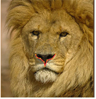
| 7. | Once you’re happy with the source curve, either: |
• draw a destination curve and use the Join ![]() tool to connect the two curves.
tool to connect the two curves.
OR
• right-click a point on the source curve and select duplicate in A and join to produce the destination curve.
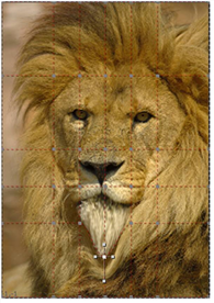
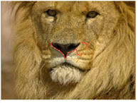
| 8. | Select the destination curve and drag points or the entire shape to a new position. The pixels in these areas are warped in the direction of movement. |
|
|
|
| The image A and warp curves. | The warped image. |
| 9. | To better see what the warped image looks like, press Q on the Viewer to toggle the overlay off. |
To compare the original and warped images, press D on the SplineWarp node to disable and enable it. If you see changes in the areas you don’t want to warp, go back to modifying your shapes.
| 10. | Using the curves list, you can quickly build up a complex warp hierarchy using the add/remove |
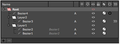
Using the root, layer, and pair warp controls, you can affect different elements as required:
• root warp - affects warp globally, irrespective of layer and pairing.
• layer warp - affects warp on the selected layers only, irrespective of pairing. This control is disabled if anything other than layers is selected.
• pair warp - affects warp on the selected pairings only. This control is disabled if anything other than pairs is selected.
Note: The pair warp value is multiplied by the layer warp value, which is in turn multiplied by the root warp value.
| 11. | If necessary, animate the source warped shapes to match any movement in the source image. For more information on how to do this, see Animating Warps. |
| 12. | You can adjust the controls described in the following table to enhance your results. |
|
Control |
What it does |
|
SplineWarp tab |
|
|
crop to format |
When disabled, the input image is not cropped to the Project Settings > full format size. As a result, warping can introduce pixels from the image outside the format size, rather than black. Note: Disabling crop to format can affect performance as Nuke has to calculate the warp for the entire image, not just the area inside the format size. |
|
bbox boundary curve |
When enabled, a boundary curve is added around the input format, limiting warp at the edges of the image. Note: In AB morph mode, the format of input A is taken as the boundary. |
|
Render Tab |
|
|
curve resolution |
Adjusts the accuracy of the warp/spline match. Higher values increase accuracy, but sacrifice speed and vice versa. For example, with open splines at low curve resolution, image tearing may occur. You can raise the curve resolution value to compensate for tearing, but the render times increase. Note: Correspondence points may be used to improve the warping accuracy in a specific part of the curve if turning this value up too high causes performance problems. |
|
boundary curve resolution |
Adjusts the number of interpolated points on boundary and hard boundary curves. Higher values stop the warp from filtering through the boundary curves but sacrifice speed, and vice versa. |
|
preview resolution |
Improves the accuracy of the preview at higher values and the rendering speed at lower values. |
|
Classic warping |
Set the type of warp function to use: • disabled - uses an updated quadratic warp function that copes well with overlapping control points, but has a more local warp effect. • enabled - employs a warping function from previous versions of Nuke that has a more global warp effect, but doesn’t cope well with overlapping control points. |
|
filter |
Select the appropriate filtering algorithm (see Choosing a Filtering Algorithm). |
Using Boundary Shapes and Pins to Limit Warp
You may notice that pixels in areas around warping are also moved to accommodate the change, but the distortion lessens the further you get from the repositioned points. If you don’t want a nearby area distorted, you can:
• Designate a curve or shape as a boundary to control or eliminate warp.
• Place pins in the areas you want to limit warp.
Note: Boundaries only affect the input they are drawn on, A or B, not both.
• Boundary - generally open splines helping to control warp rather than eliminate it.
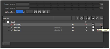
To define a boundary for an existing curve, enable boundary in the curves list, as shown below.
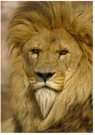
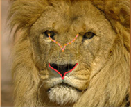
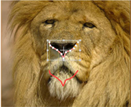
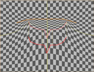
Using the example curves from Mr. Lion above, you could control the warp by adding a curve and designating it as a boundary:
|
|
|
| The source and destination curves. |
The same curves, but with a boundary above the destination to limit warp. |
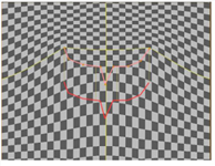
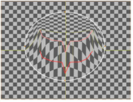
• Hard Boundary - closed shapes that eliminate warp outside the area that they enclose.
To define a hard boundary for an existing shape, enable hard boundary in the curves list, as shown below.
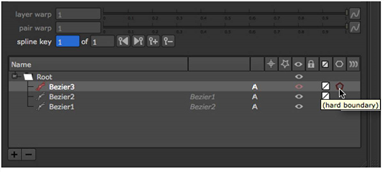
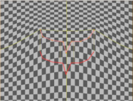
The effect of a hard boundary on a warp is quite distinct - the hard boundary, colored white by default, limits the warp effect to entirely within the closed shape:
|
|
|
• Pins - placing a pin creates a single point source and destination curve, effectively limiting warp in a very localized way.
The effect of a pin on a single joined curve is shown below. The warp direction is shown on the left and the pin’s effect on the right.
|
|
|