The Basic 3D System
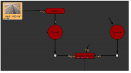
The 3D workspace is defined by a group of nodes in your script. The most basic setup includes a Camera node, a Render node, a Scene or Geometry node, and nodes that provide the 2D images you want to pipe into the 3D compositing space.
|
|
| The basic 3D node tree: 2D image, geometry, scene, render, and camera. |
The 3D Viewer
Once you have the 3D node structure, you can use any Viewer in Nuke as a gateway to the 3D compositing space. Choose 3D from the view dropdown menu, or press the Tab key over the Viewer to toggle between the 2D and 3D views.
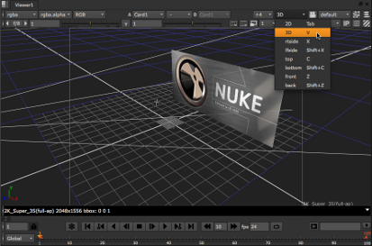
On the view dropdown menu, you’ll also see orthographic views - rtside, lfside, top, bottom, front, back - which provide non-perspective views into the scene. In three-quarter perspective, it can be difficult to accurately place objects on the axes, and the non-perspective views make it easier to line things up.
The Geometry or Scene Node
Every 3D system needs a piece of geometry - a card, a sphere, a cube, something - to receive an image or clip that the camera can “see.” One is all you need, but you can setup complex systems with a large amount of 3D data. When you have two or more objects for a 3D system, you need a Scene node to create a “place” where the camera (and the ScanlineRender node) can see all the objects at once.
The Camera Node
The Camera node creates your view into a scene. It has several controls to help you match the properties of a physical camera. You can animate its position or import animation or tracking data to matchmove your 3D scene with a background plate. A 3D system can have multiple cameras connected to the Scene node, to create different views on a 3D scene.
Tip: Only one camera can be connected to the ScanlineRender node to generate the output, but you can insert multiple ScanlineRender/Camera node pairs to generate output from various perspectives.
The ScanlineRender Node
The last node, ScanlineRender, sends the results of your 3D scene back into your composite as a 2D image. It’s always 2D in, 3D manipulation, and then 2D back out, which is why this is often called “2-and-a-half-D.”
|
|
| The scanline render node converts the image back to 2D. |
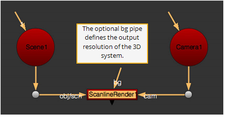
The image created by the ScanlineRender node is the same resolution as your project settings. When you need to render a specific resolution, use the optional bg pipe. Connect a Constant node with the resolution you want and that defines the output of the ScanlineRender node.
So now you know the basic 3D setup for your compositing script. Let’s take a test drive.