Using O_MultiSample
You can use O_MultiSample with only the Sample input to fill in holes or replace data, or you can use O_MultiSample with the Mask and Sample input, to apply the sample data to a different area specified in the Mask input.
Using O_MultiSample with the Sample Input
You can use O_MultiSample to replace an area of channel data that is not accurate. For example, if you have generated a disparity map and there is a section that you are not happy with, you can use O_MultiSample to fill the specified shape with the surrounding disparity vector data from the whole image. This means that the disparity vectors in the selected area are replaced.
To use O_MultiSample to remove an area of disparity, you can do the following:
|
1.
|
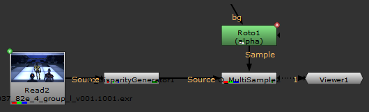
If disparity vectors do not already exist in the image sequence, insert an O_DisparityGenerator node after your image sequence to calculate the disparity vectors. See DisparityGenerator for more information. |
|
2.
|
Select Ocula > Ocula 4.0 > O_MultiSample to insert an O_MultiSample node, either after the O_DisparityGenerator node if you added one in the previous step, or after the image sequence. |
|
3.
|
Create a Roto node and connect it to the Sample input of the O_MultiSample node. |
|
4.
|
Connect a Viewer to the O_MultiSample node. Your node tree should now look something like this: |
|
5.
|
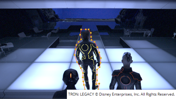
Open the Roto controls. Draw a bezier around the area of disparity you want to remove. |
|
6.
|
Select disparity from the channel dropdown. Select Luminance from the RGB dropdown. |
|
7.
|
Adjust the gain and gamma controls to display the disparity map more clearly. |
|
8.
|
Open the O_DisparityGenerator controls. You can set the Strength control to 2, and the Smoothness control to 3. |
|
9.
|
Open the O_MultiSample controls and set the Channels control to disparity. |
|
10.
|
Set the Sample control to Sample Inverted Alpha. This removes the disparity from the selected area by filling it using the surrounding disparity vector data. |
|
|
|
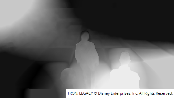
The original left view disparity map.
|
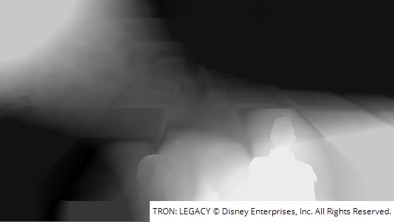
The left view with the selected area of
disparity removed.
|
Using O_MultiSample with the Sample and Mask Inputs
You can use O_MultiSample to correct a specific area with data from the defined sample area. For example, if you use O_NewView to create a new left view and an area of it doesn't build correctly, you can use O_MultiSample to correct it.
In this case, you first create a new view:
|
1.
|
O_NewView requires disparity vectors to operate correctly. If disparity vectors do not exist already, insert an O_DisparityGenerator to calculate them either after the image sequence, or – if you added one – the JoinViews node. |
|
2.
|
O_NewView also requires an O_OcclusionDetector node. Insert this after the O_DisparityGenerator node. |
|
3.
|
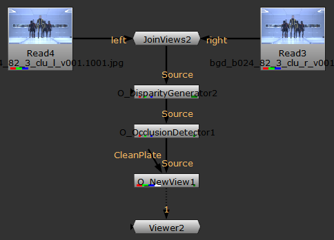
Select Ocula > Ocula 4.0 > O_NewView to insert an O_NewView node and attach a Viewer to the O_NewView node. Your node tree should now look something like this: |
|
4.
|
In the O_NewView controls, select Left from Right from the View to Build dropdown to rebuild the left view using the pixels from the right. |
|
|
|
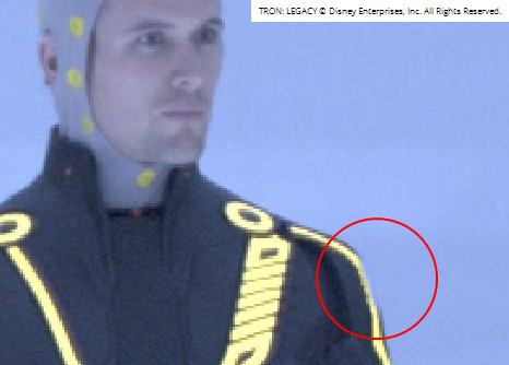
The rebuilt left view from the right.
Notice the shoulder has not been
reconstructed correctly.
|
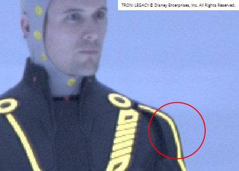
The original right view.
|
In this case, the left view has not been reconstructed correctly as a result of an irregular area in the disparity. This can be corrected by using O_MultiSample:
|
5.
|
Insert an O_MultiSample node before the O_NewView node. |
|
6.
|
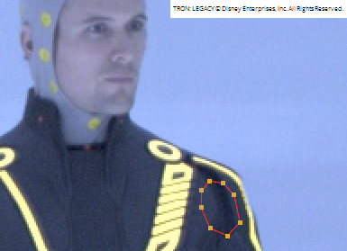
Create a Roto node and attach it to the Sample input of O_MultiSample. Draw a bezier around an area of disparity that you want to sample. In most cases, sampling the disparity from an area that is close produces the best results (see screenshot below). In this case, we need to sample the disparity from a close area at the same depth / or surface to get the best result. |
|
7.
|
Create a RotoPaint node and attach it to the Mask input of O_MultiSample. Your node tree should now look something like this: |
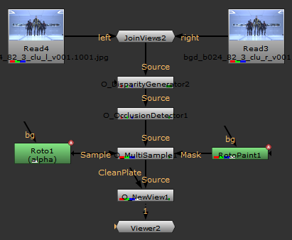
|
8.
|
From the RotoPaint node, use a paint brush to paint a stroke over the area of disparity that you want to correct. To view the stroke on the image, connect the bg input of the RotoPaint node to the O_DisparityGenerator node and then attach the RotoPaint to Viewer. Choose to display Viewer input 2. Your node tree should now look something like this: |
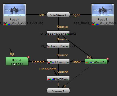
In this case, when you have the node tree set up like this and you display Viewer input 2, this is what you see:

|
9.
|
Choose to display Viewer input 1. |
|
10.
|
Open the O_MultiSample controls, set the Channels control to disparity. |
|
11.
|
Set the Sample control to Sample Alpha, and the Mask control to Mask Alpha. This now fills the area specified area in the Mask input, with the data sampled from the specified area in the Sample input. In the image, the painted area is now rebuilt correctly. To compare the result to the original, press D several times with the O_MultiSample node selected, to disable and re-enable it. |

|

|
|
The image with the O_MultiSample node disabled, showing the incorrectly built shoulder.
|
The image with the O_MultiSample node enabled, showing the correctly rebuilt view.
|