Search is based on keyword.
Ex: "Procedures"
Do not search with natural language
Ex: "How do I write a new procedure?"
AttributeSet Nodes
Making Changes with the AttributeSet Node
To add an AttributeSet node to a recipe:
| 1. | Create an AttributeSet node and connect it to the recipe at the point you want to make the change. |
| 2. | Select the AttributeSet node and press Alt+E. |
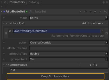
The AttributeSet node becomes editable within the Parameters tab.
| 3. | Select the assignment mode from the mode dropdown: |
• paths - the locations influenced by this node are selectable by their path.
• CEL - the locations influenced by this node are selectable using CEL.
| 4. | Assign the locations to influence with this node to either the paths or celSelection parameter (depending on your selection in step 3). |
| 5. | Select what type of action this node is performing: |
• Create/Override - adds a new attribute or overrides an existing one.
• Delete - if it exists, removes an attribute from the location.
• Force Default - forces the attribute back to its default.
| 6. | Enter the name of the attribute to influence in attributeName. |
You can enter a grouped attribute by separating the parts of the attribute with a . (period), for instance geometry.point.P.
If the action parameter is Create/Override:
| 7. | Select the type of the attribute using the attributeType dropdown. |
| 8. | With the groupInherit parameter, select whether you want the attribute changes to be inherited by any scene graph children. For instance, a new attribute on /root/world/geo created with this option set to Yes is inherited by all children of /root/world/geo. |
| 9. | Enter the new attribute value in the <type>Value parameter, for instance, stringValue for a string. |
Tip: It is possible to middle-click and drag from an attribute in the Attributes tab to the Drop Attributes Here hotspot in an AttributeSet node’s Parameters tab to automatically create a field to set the dragged attribute.
Using Material Underlays with the AttributeSet Node
In addition to editing attributes with the AttributeSet node, as described above, you can use the node to create material underlays. Attributes from an underlayAttrs group attribute that is part of a material group attribute are copied to the top level of a location's attributes during the MaterialResolve step.
This only happens if matching attributes are not already set on the target location (the location that points at the material using materialAssign). This allows, for example, custom renderer object settings to be specified for locations, which can be overridden by any locally-set values.
To set a material underlay:
| 1. | Add a PrimitiveCreate node and set its name to /root/world/geo/teapotYellow. |
Set type to teapot and Z translate to -2.5, and Y rotation to 180.
| 2. | Add another PrimitiveCreate node (or copy and paste the exisiting one) and set its name to /root/world/geo/teapotPink. |
Set type to teapot, Z translate to 2.5.
| 3. | In the Node Graph, select both Primitive Create nodes and press M to merge. |
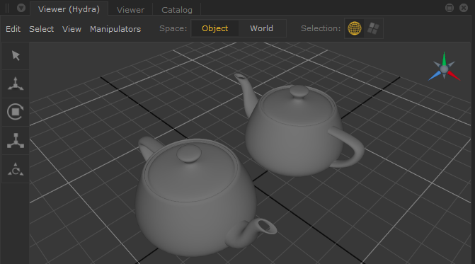
| 4. | Expand the Scene Graph to view the primitives. The image below shows the scene in the Hydra Viewer. |
| 5. | Add a yellow material node: |
Add a Material node.
In the Parameters tab, change it’s name to Yellow.
Click Add Shader and pick dl > Surface to add a dlSurfaceShader. From the dropdown select dl3DelightMaterial.
Change the Base Layer > Diffuse and Subsurface > Color value to 0.5, 0.5, 0.0.
| 6. | Add a pink material node: Repeat step 5 but change the name to Pink and the color to 0.5, 0.0, 0.5. |
| 7. | Add a MaterialAssign node. Assign the yellow material to the yellow teapot: |
Middle-mouse +drag the teapotYellow mesh item from the Scene Graph tab to the CEL field's Add Statements button on the Parameters tab for the MaterialAssign node.
Middle-mouse+drag the Yellow material from the Scene Graph to the materialAssign field.
| 8. | With a new MaterialAssign node repeat step 9, but assign the Pink material to the teapotPink mesh. |
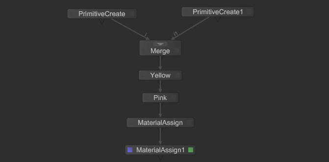
| 9. | Your node graph should be connected as follows: |
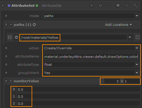
| 10. | Add an AttributeSet node and connect it to the bottom of the graph. Middle-mouse+drag the Yellow material from the Scene Graph on to the CEL path field and set the following parameters: |
action: Create/Override
attributeName: material.underlayAttrs.viewer.default.drawOptions.color
attributeType: float
groupInherit: Yes
numberValue: 3 x 1, with 0: 0.5, 1: 0.5 and 2: 0.0.
| 11. | Copy and paste the AtrributeSet node and connect it to the previous node. On this new node assign the Pink material to the path and set the number values to 0.5, 0.0 and 0.5 respectively. |
Note: If you inspect the materials in the Attributes tab, you will notice an attribute has been created under a tab called underlayAttrs for both materials. 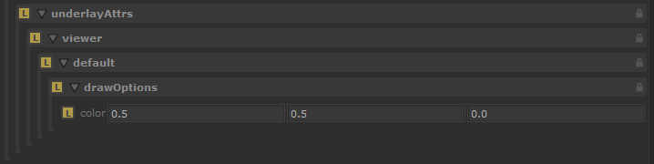
Inspecting both teapot mesh items will show their viewer.default.drawOptions attributes at the default values.
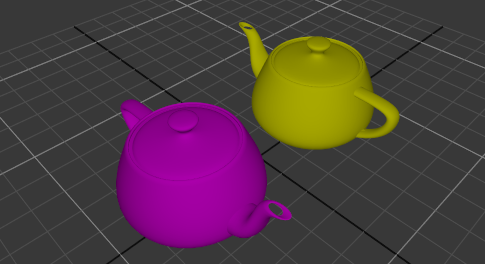
| 12. | Add a MaterialResolve node and connect it to the previous node. The underlay attributes are transferred to the teapots and override their default Hydra view. |
To deactivate the node and return to the default, highlight it and press D.
| 13. | Copy and paste the second AttributeSet node, and connect the newly created node in between the second AttributeSet node (for the pink material) and the MaterialResolve node. |
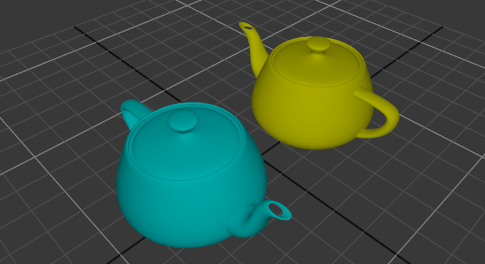
| 14. | In the new AttributeSet node, change the CEL field to point at the teapotPink location rather than the pink material. In the attributeName field, change the value to viewer.default.drawOptions.color, and the numberValue to 0.0, 0.5, 0.5. |
You will now see the material underlay attribute is only affecting the yellow teapot at resolve time.
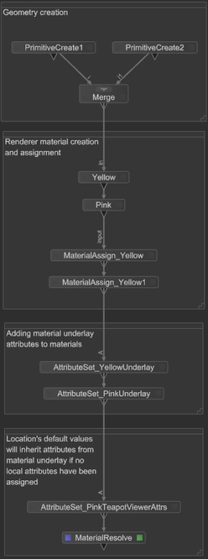
Here's the full node graph for reference with nodes renamed for clarity:
Sorry you didn't find this helpful
Why wasn't this helpful? (check all that apply)
Thanks for your feedback.
If you can't find what you're looking for or you have a workflow question, please try Foundry Support.
If you have any thoughts on how we can improve our learning content, please email the Documentation team using the button below.
Thanks for taking time to give us feedback.