Creating Shading Networks
This topic explains how to use the NetworkMaterialCreate node to build a shading node network.
Note: To learn about the NetworkMaterialCreate node parameters, see NetworkMaterialCreate.
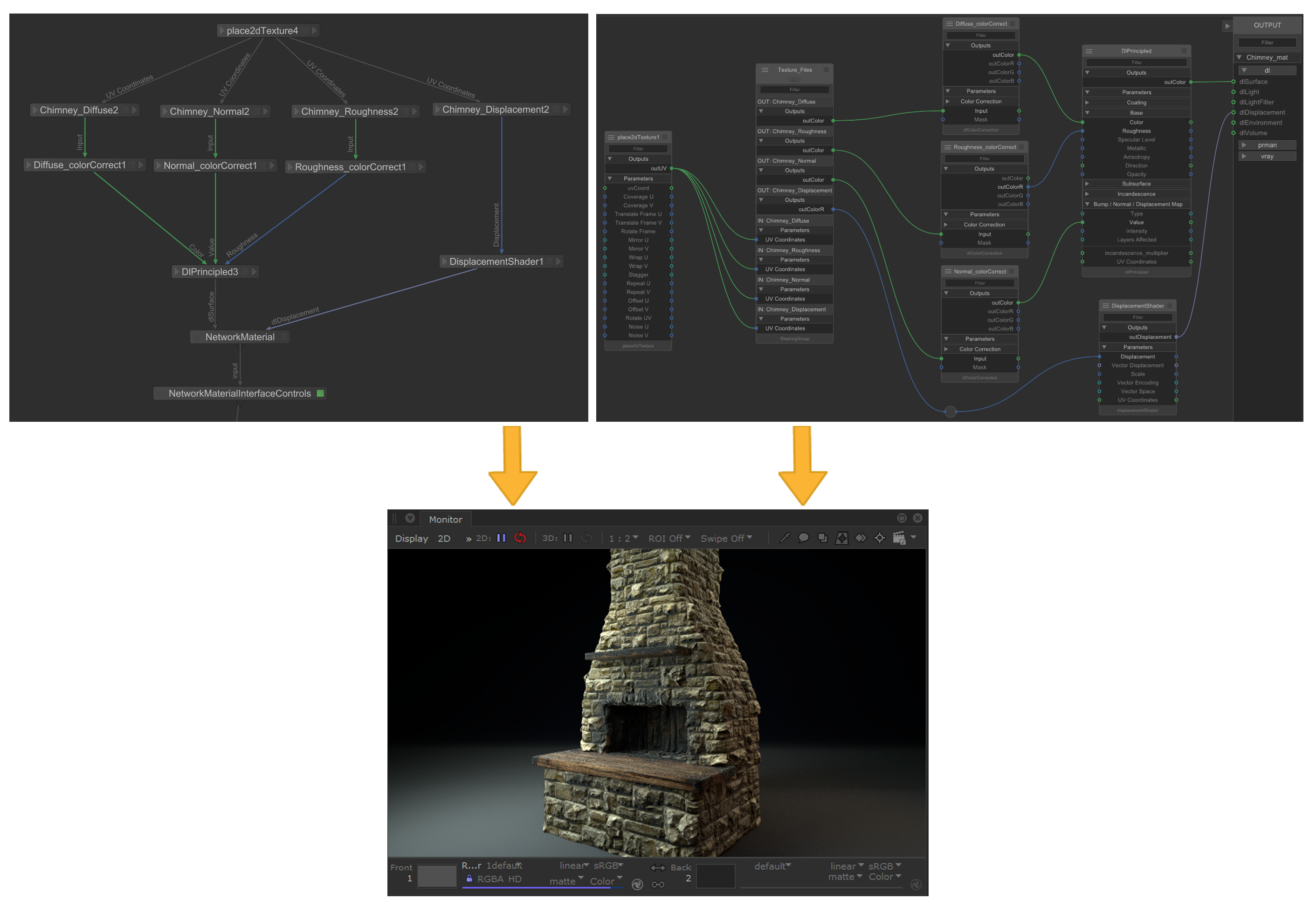
This example illustrates the difference between the previous, and new workflows for building materials. Both networks function in the same way and have the same end result.
|
Previous NetworkMaterial workflow VS current NetworkMaterialCreate workflow Rendered result for both workflows |
NetworkMaterialCreate Overview
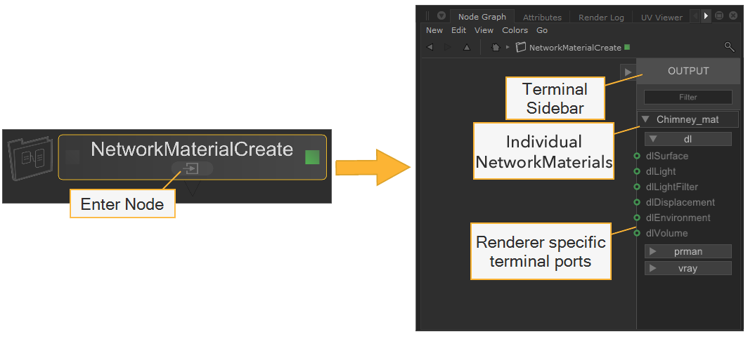
The NetworkMaterialCreate node is created in the same way as any other node, hit Tab, select it from the menu and place it in your node graph. To jump inside the node, you can:
- Ctrl + Middle-mouse click on the node.
- Click the enter node
 button.
 - Select the node and hit Ctrl + Enter.
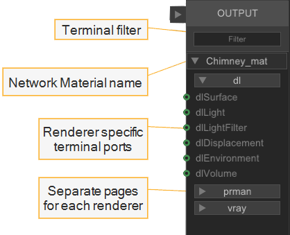
Inside the NetworkMaterialCreate node is a fixed sidebar on the right, which shows each NetworkMaterial and their terminals for each renderer you have set up with Katana. This sidebar functions in the same way as the Network Material node in the previous workflow, but all the terminals are prepopulated so the user doesn’t need to add them manually. The sidebar can be hidden and exposed using the collapse  and expand
  tabs.
tabs.
Note: By default, a NetworkMaterialCreate node provides one NetworkMaterial location. If you would like to discover how to set up multiple NetworkMaterial locations within one NetworkMaterialCreate node, see Multiple NetworkMaterials with NetworkMaterialCreate.
|
The NetworkMaterialCreate node |
Inside the NetworkMaterialCreate node |
At the top of this bar there is a Filter which allows you to enter a string to search for a specific terminal. For example, start typing ‘displacement’ and the list filters down to only show the terminals containing the word displacement. This is useful especially if you have multiple renderers or NetworkMaterials set up.
Under the Filter bar is the name of your Network Material, you can rename this from the Parameters tab, by double clicking your Network Material or selecting it and pressing Enter on the keyboard.
|
The fixed terminal sidebar |
Note: Renaming the node itself won’t change the name you’ll see on the terminal sidebar. The Network Material name can be changed from the Parameters > Node Parameters tab.
The Node Menus
To create a shading node, press Tab from inside a NetworkMaterialCreate node to bring up the node creation menu, and type the node name. As you're typing, the menu will filter down. When inside a NetworkMaterialCreate node, the menu is limited to show your default renderer nodes, and a few standard Katana nodes, only the nodes you are able to use are visible.
The nodes have a colored stripe on the left to indicate whether they belong to a renderer or whether they are standard Katana nodes. For example, the 3Delight shading nodes are color-coded with a red stripe and the Katana nodes appear yellow.
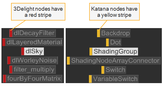
| Colored stripes in the node creation menu indicate group type |
You can alter the node menu to display shading nodes from your other renderers. To do this:
- Hold Shift and hit Tab.
- Select the required renderer.
- Hit Tab again to bring up the node menu for your selected renderer.
The S key is a 3Delight keyboard shortcut which brings up the node creation menu for 3Delight shading nodes. This can be useful if you want to switch back and forth between two renders as you can use the S key to bring up 3Delight shading nodes whilst using Tab to bring up the node menu for a different renderer.
|
Tab |
Node menu for selected renderer. |
|
S |
Node menu for 3Delight shading nodes. |
|
Shift+Tab |
Select renderer to change node menu. |
Note: It is possible to change the nodeType from within a shading node's parameters. Values of any parameter names that overlap between node types will be remembered and no changes will be lost if you want to switch back and forth.
Connecting Shading Nodes
Setting up shading nodes within the NetworkMaterialCreate node is designed to make things as simple as possible for artists. Shading networks set up inside the group feature a left-to-right workflow which is well suited to working with a large number of shading nodes.
The shading nodes themselves are designed and optimized for creating materials, as the input and output ports are all visible and clearly labeled.
Tip: You can rename the shading nodes by selecting the node, hitting Enter, and typing the new name. You can also show and hide the Filter function on selected nodes using the Alt+Enter keyboard shortcut.
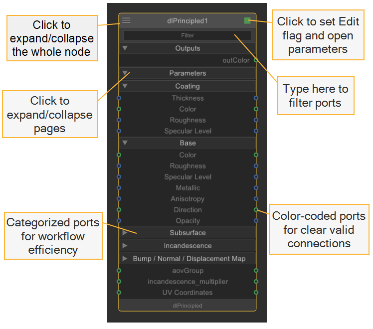
| Shading Node UI |
Tip: Some pairs or groups of nodes that are normally used together or that rely on each other, are automatically created when you place one of the nodes. For example, if you place a file node, a place2DTexture node is automatically created.
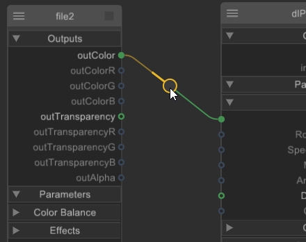
To link shading nodes together, click once on a parameter port to begin drawing the connection, and then click once on the other shading node's port to connect the two nodes together. Invalid target ports are grayed out and disabled to show which connections are available.
The input and output ports are all color-coded to indicate which connections can be made. You can only connect the compatible data types, for example, int to int and float to float.
Tip: Hover your cursor over the input/ouput port to see what data type it provides/receives
Data Type Color Codes:
|
color |

|
float / array_float |
|
int |

|
matrix |

|
normal |

|
point |

|
string |

|
vector |
|
disabled |
|
misc |
| Connecting shading nodes |
Once your shading nodes are connected to the terminal sidebar, the network is now set up and your NetworkMaterial is in your Scene Graph under /root/materials by default.
Note: To learn how to change your NetworkMaterial scene graph location and other NetworkMaterialCreate parameters, see NetworkMaterialCreate.
Tip: In the same way as the terminal sidebar, you can type in the Filter field of the shading nodes to quickly search for an input/output, even if the menu is not expanded. You can show and hide the Filter function on selected nodes using the Alt+Enter keyboard shortcut.
The arrows on the shading nodes show if a page is expanded:
-
 - A downwards-facing arrow means the page is expanded.
 -
 - A right-facing arrow means the page is collapsed.
You can click on the page titles to expand/collapse pages so that you can hide certain sections. To collapse/expand the entire shading node, you can click the expand/collapse state button ![]() at the top-left of a node or use the keyboard shortcuts:
at the top-left of a node or use the keyboard shortcuts:
Tip: You can use the preference nodegraph > defaultShadingNodeViewState to set the default expand/collpase state of new nodes.
- ALT + 1 - Collapse completely.
- ALT + 2 - Expand to show connected ports.
- ALT + 3 - Fully expand pages and connections.
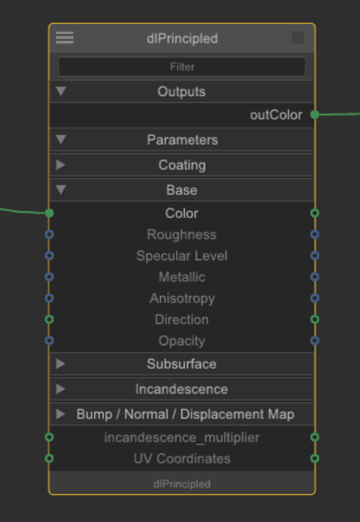
Tip: The example shows just connections exposed, but you can expose the pages containing the connected inputs and outputs, such as Base by enabling the showPagesConnectedOnly control in the Preferences under nodegraph.
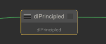
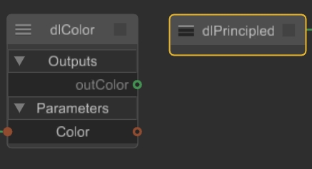
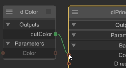
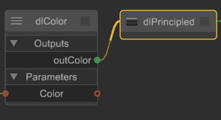
If a node is collapsed, you can drag a connection over the node to automatically expose compatible connections. The node collapses again automatically after connecting the input or output. The same is true if you change you mind and drop the connection outside the node.
|
|
|
|
A collapsed dlPrincipled target node with no exposed connections |
Dragging a connection over the node auto-expands compatible connections |
|
|
|
|
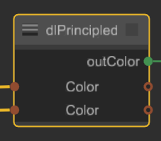
The auto-collapsed node after a connection is made |
|
Organizing a Shading Network with Dot Nodes
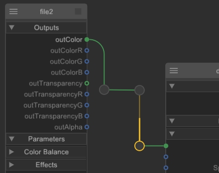
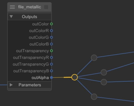
Dot nodes can help you organize complex shading networks to make them easier to read. For example, you can bend connections around notes for other artists or use a Dot to connect a single output to multiple inputs.
|
|
|
|
Using Dot nodes to bend connections |
Splitting an input using a Dot node |
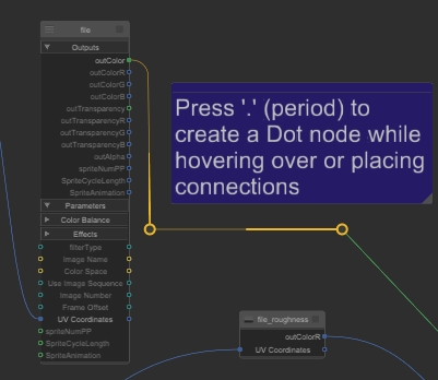
You can add a Dot like any other node, by pressing Tab and then typing Dot into the node finder, but the fastest way to add a Dot node is to press . (period) on your keyboard. Like other nodes, the Dot node sticks to your pointer and you can click anywhere in the shading network to place it.
Alternatively, you can add Dot nodes when hovering over a connection to insert the Dot between nodes or you can drag a node output and then add a Dot node to create a Dot chain.
|
|
|
|
Adding a Dot node to a connection |
Adding multiple Dot nodes to create a chain |
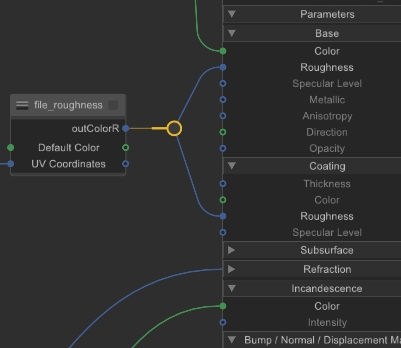
Dot nodes in shading networks are omnidirectional, meaning you can connect to them and drag outputs from them in any direction. They can have as many output connections as you like, but only one input connection.
Hiding Node Connections
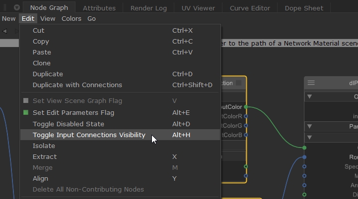
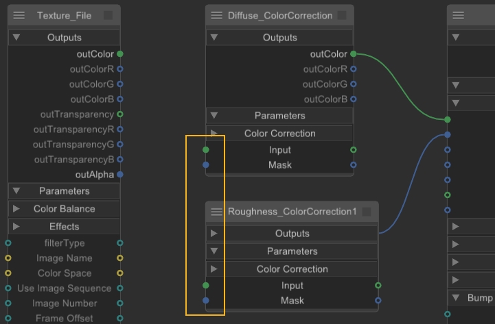
In node-heavy shading networks, the connections between nodes can cause confusion if you're looking for a particular input. You can show and hide node input connections to clean up the network by navigating to Edit > Toggle Input Connection Visibility or by using the Alt+H keyboard shortcut.
Tip: You can also show and hide the Filter function on selected nodes using the Alt+Enter keyboard shortcut.
-
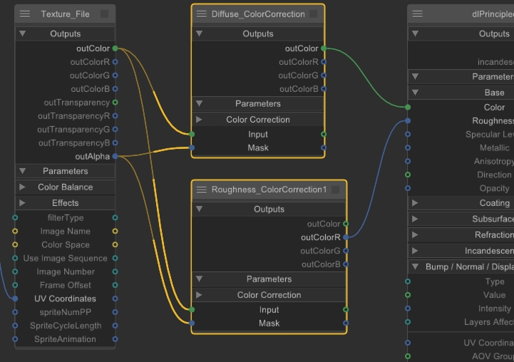
Select the node or nodes you want to affect in the shader tree. In this example, the Diffuse and Roughness nodes.
-
Navigate to Edit > Toggle Input Connection Visibility or use the Alt+H keyboard shortcut to hide the input connections on the selected nodes.
-
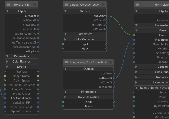
Deselect the nodes to see the effect.
-
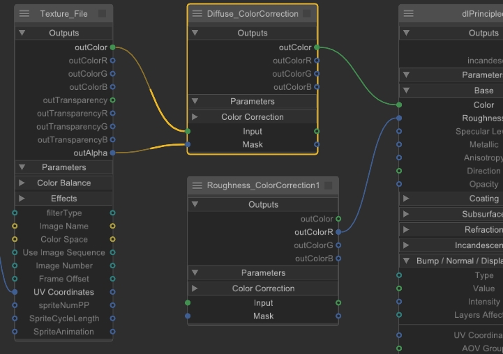
You can select a node in the tree to temporarily display its input connections.
-
When the inputs are hidden, the connections on the node are still filled to indicate that a hidden connection exists.
-
Select the nodes and navigate to Edit > Toggle Input Connection Visibility or use the Alt+H keyboard shortcut to show the input connections on the selected nodes.
-
Tip: Hold Alt+H with no selection to temporarily show hidden connections.