Search is based on keyword.
Ex: "Procedures"
Do not search with natural language
Ex: "How do I write a new procedure?"
Contact Support
Node Graph
The Node Graph is essentially another way of viewing and managing channels, layers, and shaders. You can set up a Node Graph for ordering different sets of paint and combine effects in a non-destructive manner, just like layers, but the Node Graph allows you to micro-manage the various components as individual nodes.
Mari's Node Graph has two modes, Basic and Advanced, exposing different levels of detail within the palette. Basic mode, only allows you to work with graph layers from the Layers palette. Advanced mode, the default mode, exposes the channels, layers, and so on, in the Node Graph palette.
Note: You can enable the Advanced Node Graph in the Mari Preferences dialog under Node Graph > General > Advanced View.
The Node Graph and Node Properties palettes are not displayed in the default layout, so to view the Node Graph, navigate to View > Palettes > Node Graph.
|
|
|
|
A simple graph layer in Basic mode. |
A simple node tree in Advanced mode. |
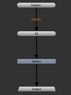
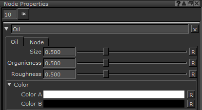
The Node Graph contains nodes and each node has properties specific to the node's purpose located in the Node Properties palette. The Node Properties palette is also located in View > Palettes, but the fastest way to open a node's properties is to double-click it in the Node Graph.
For example, the Oil node has controls for Size and Color to determine the look of the oil effect. See
If you prefer working with layers, you can build a layer stack as normal, using channels and shaders, and Mari automatically replicates it in the Node Graph. See Layers and Adding Graph Layers for more information.
Objects, Channels, Layers, and Shaders Within the Node Graph
At first glance, the Node Graph that Mari creates automatically from layers can seem a little chaotic, but each element corresponds to a familiar concept. For example, importing a simple .obj creates the following Node Graph.
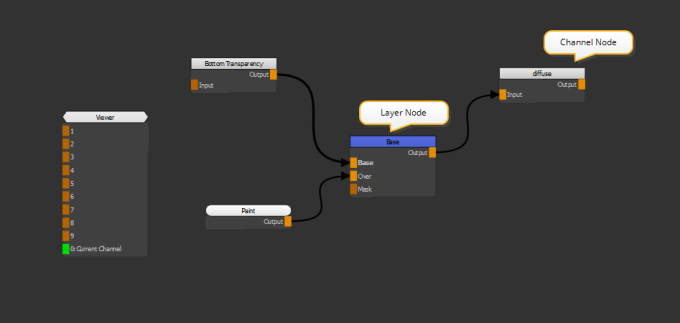
Each Node Graph represents a single object and, just like in the layer system, each channel contains layers, including a Bottom Transparency layer. In the example, a Base layer is also included. If you add more layers to the channel, they appear under the first layer.
Tip: In Mari's Node Graph, you can either navigate from left-to-right (default), also called No Port List, or top-to-bottom, also called Show Port List, similar to the Layers palette. You can set the navigation type in the Mari Preferences Dialog. You can also switch the navigation directly in the Node Graph, either use Shift+S or right-click and select Node Graph > Edit > Toggle Port List.
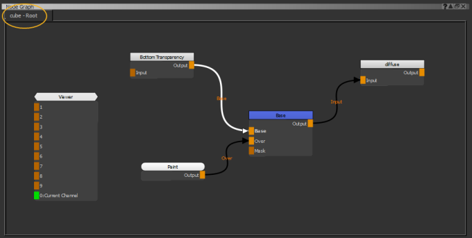
If a project contains multiple objects, the Node Graph Root name changes to represent the currently-selected object. For example, selecting an object called cube changes the Node Graph label to cube - Root.
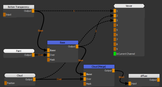
You can use the Viewer node to examine your node tree at any point to help you get to grips with how the Node Graph represents the Layers palette. Select the node you want to view and press 1 on the keyboard to connect the Viewer node. You can connect up to 9 nodes to the Viewer node. The 0 input of the Viewer node is automatically connected to what is selected in the Shaders palette.
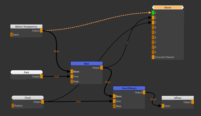
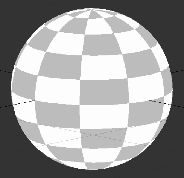
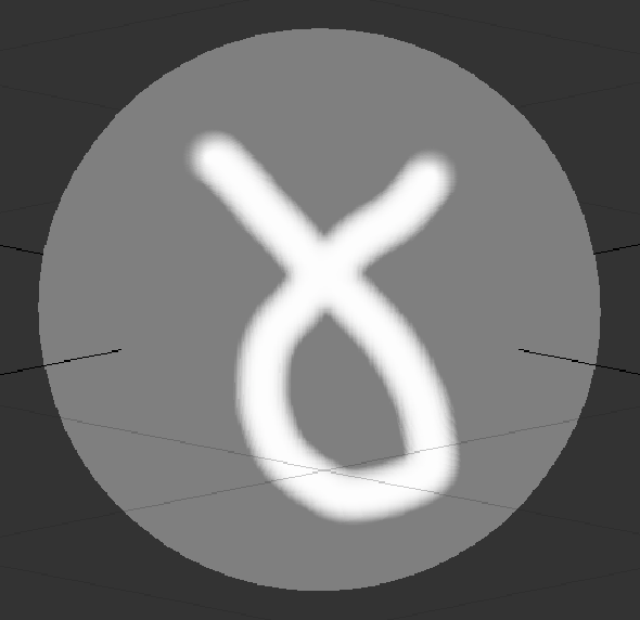
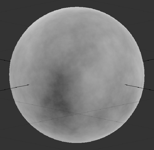
In the example, attaching the Viewer to the Bottom Transparency, Base (including paint in the Paint node), and Cloud nodes in succession produces the following results:
|
|
|
|
| Bottom Transparency | Base Layer, with Paint | Cloud Procedural |