Search is based on keyword.
Ex: "Procedures"
Do not search with natural language
Ex: "How do I write a new procedure?"
Triplanar Projection Node
Access: Nodes > Projection > Triplanar Node
Using the Triplanar node to quickly texture hard surface assets with poorly laid out UVs.
The Triplanar Projection node is a node which allows you project up to 3 different images from the 3 different axis of your mesh in 3d space.
It is similar to the Tiled node however it does not rely on an objects UVs, so it is great for hard surface texturing, such as bricks or tiles, which would look odd if there was UV stretching or squashing. Unlike the Tiled node, it allows multiple images at once giving you a greater level of control.
The Triplanar Projection node can also be great if a Tiled node is giving obvious seams at UV shell borders.
Tip: In some instances a Tiled node may be better on curved surfaces, as a Triplanar Projection node can give strange and blurred results in those scenarios.
Triplanar Projection Node Inputs
Position: The node works in 3d space, but by adding a node to the Position input you can manipulate how the projection is applied. Examples include the UV node to use a UV space rather than 3D space. This helps if you want to apply 3 different images to different axis but still retain UV direction, stretch, and squash.
Normal:Overrides the surface normals used to define how the top front side projections are mapped to the object.
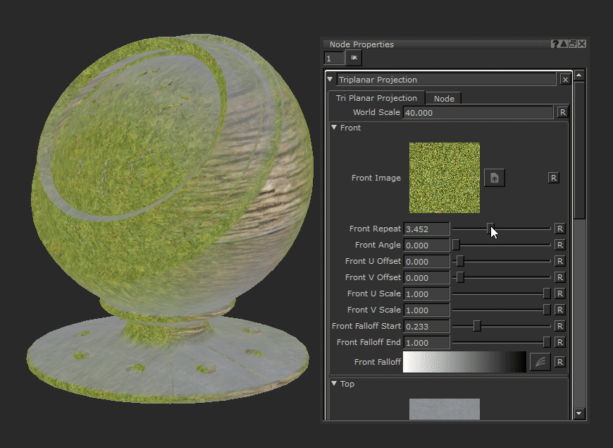
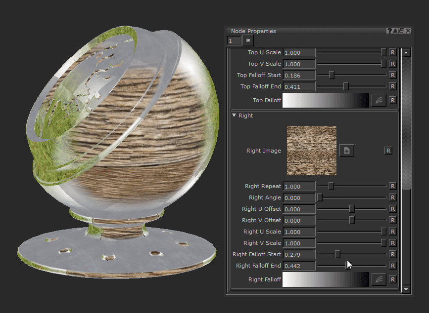
Triplanar Projection Node Properties
The following example images will be using a different image on each axis for demonstration purposes.
|
World Scale Text field |
Changes the overall scale of all 3 projected images at once - front, top, and right. This saves you having to change the repeat amount of all the images individually if you want to do a uniform scale of the projections.
Default is 4. |


Front
|
Front Image image |
Chooses the image to project across the front of your geometry. |
||||||
|
Front Repeat Text field, slider |
Changes the tiling amount of your projected image. Increasing this value makes the image scale down.
Default is 0. |
||||||
|
Front Angle Text field, slider |
Changes the rotation of the projected image.
Default is 0. |
||||||
|
Front U Offset Text field, slider |
Moves the tiled image horizontally along the U axis of the projection.
Default is 0. |
||||||
|
Front V Offset Text field, slider |
Moves the tiled image vertically along the V axis of the projection.
Default is 0. |
||||||
|
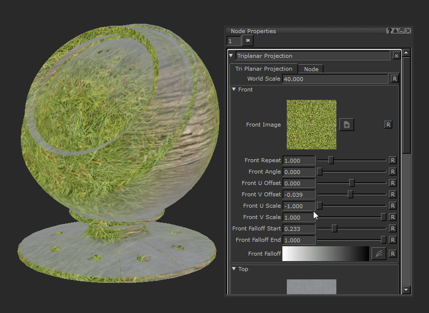
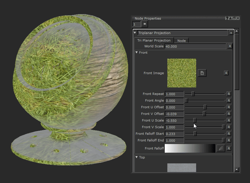
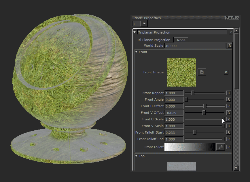
Front U Scale Text field, slider |
Scales the tiled image horizontally along the U axis of the projection. If this number is higher than the V Scale the image will start to elongate vertically.
Default is 1. |
||||||
|
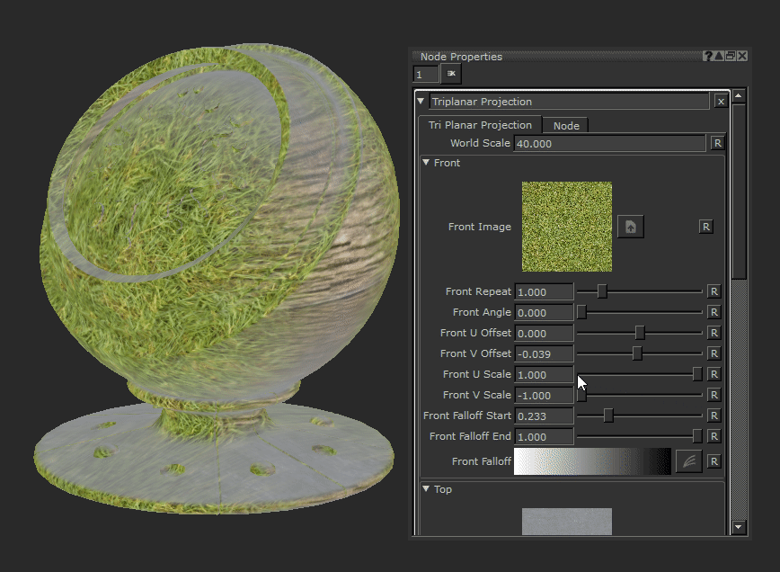
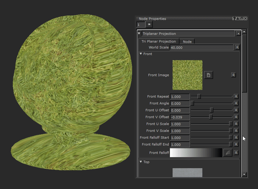
Front V Scale Text field, slider |
Scales the tiled image vertically along the V axis of the projection. If this number is higher than the U Scale the image will start to elongate horizontally .
Default is 1. |
||||||
|
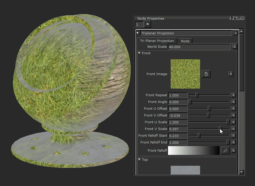
Front Falloff Start Text field, slider |
Changes the fall off of the front projection and the threshold at which angles the projection will cover.
Raising this slider will make the projection cover more area on curved or glancing angles and may eventually overlap the other axes projections. Default is 0. |
||||||
|
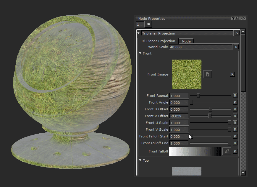
Front Falloff End Text field, slider |
Changes the fall off of the front projection and the threshold at which angles the projection will cover.
Lowering this slider will make the projection cover less area on curved or glancing angles. Default is 1. |
||||||
|
Front Falloff Curve editor |
This curve editor gives control of the falloff of the front projection - by manipulating the curve you can make the falloff harsher. This may be useful when texturing hard surface assets to avoid soft and blended textures. |


Top
|
Top Image image |
Chooses the image to project across the top of your geometry. |
||||||
|
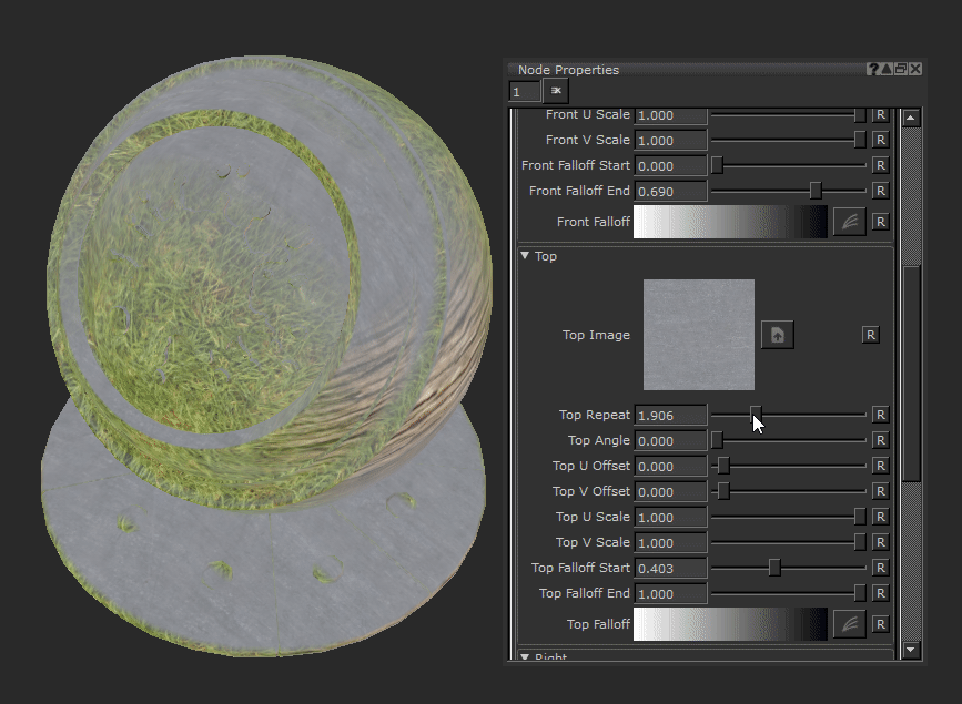
Top Repeat Text field, slider |
Changes the tiling amount of your projected image. Upping this value will make the image scale down.
Default is 0. |
||||||
|
Top Angle Text field, slider |
Changes the rotation of the projected image.
Default is 0 |
||||||
|
Top U Offset Text field, slider |
Moves the tiled image horizontally along the U axis of the projection.
Default is 0. |
||||||
|
Top V Offset Text field, slider |
Moves the tiled image vertically along the V axis of the projection.
Default is 0. |
||||||
|
Top U Scale Text field, slider |
Scales the tiled image horizontally along the U axis of the projection. If this number is higher than the V Scale the image will start to elongate vertically.
Default is 1. |
||||||
|
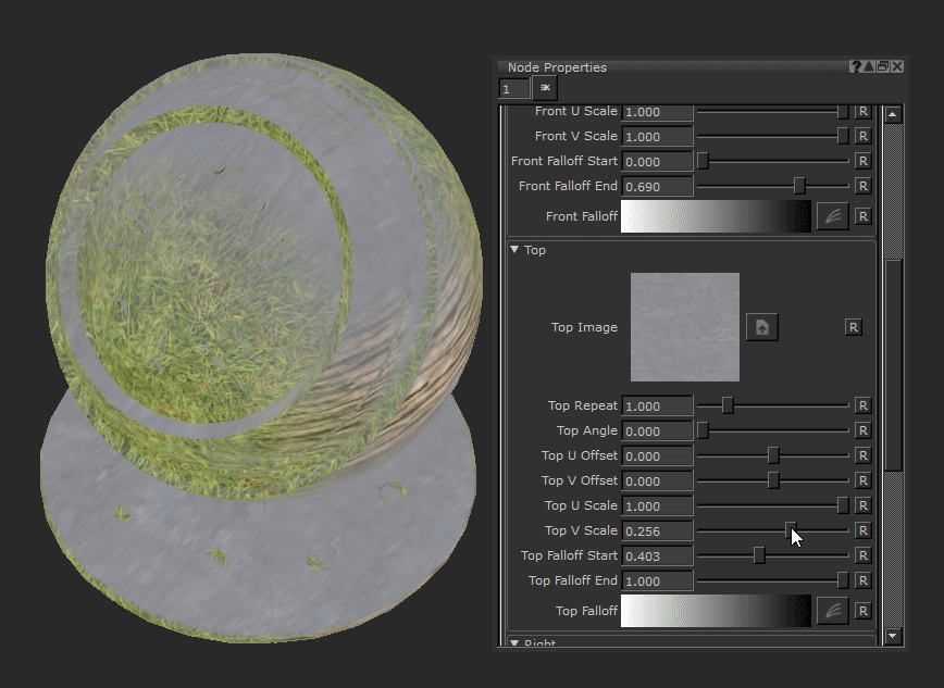
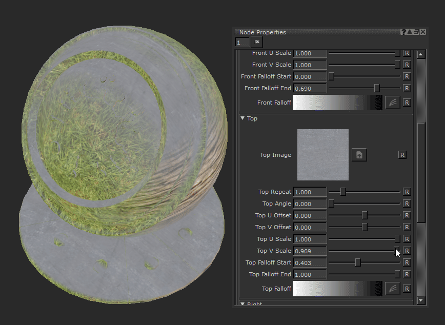
Top V Scale Text field, slider |
Scales the tiled image vertically along the V axis of the projection. If this number is higher than the U Scale the image will start to elongate horizontally.
Default is 1. |
||||||
|
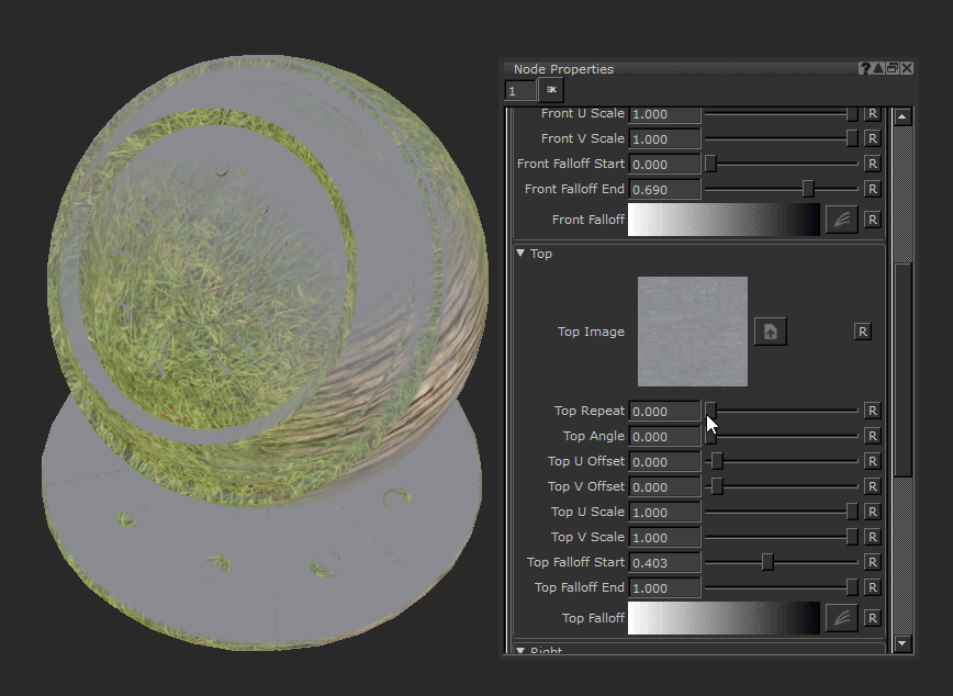
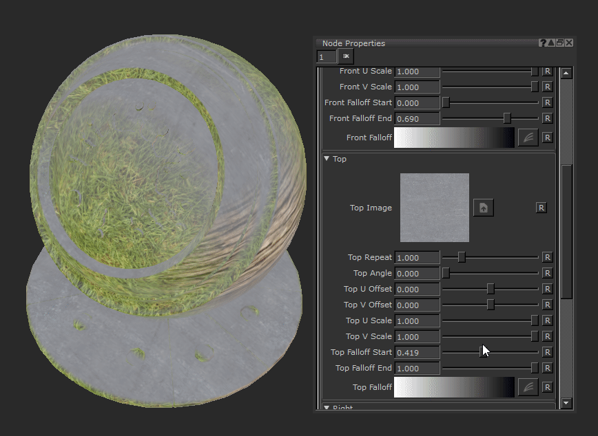
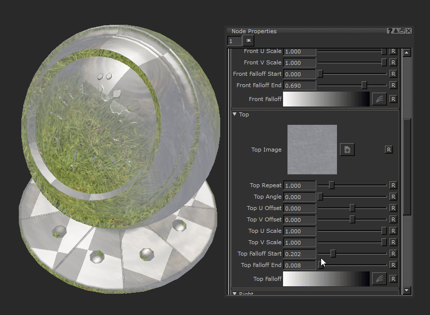
Top Falloff Start Text field, slider |
Changes the fall off of the top projection and the threshold at which angles the projection will cover. Raising this slider will make the projection cover more area on curved or glancing angles and may eventually overlap the other axes projections.
Default is 0. |
||||||
|
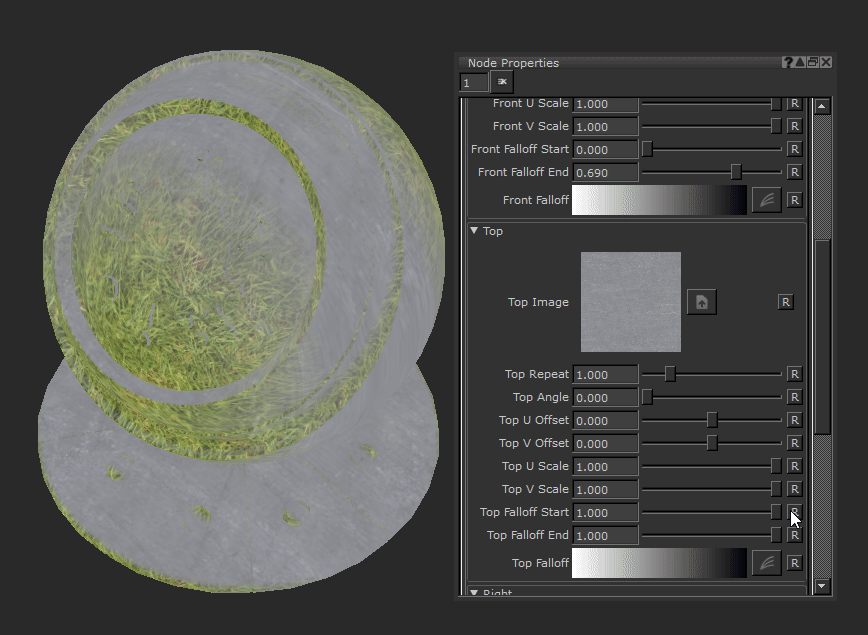
Top Falloff End Text field, slider |
Changes the fall off of the top projection and the threshold at which angles the projection will cover. Lowering this slider will make the projection cover less area on curved or glancing angles.
Default is 1. |
||||||
|
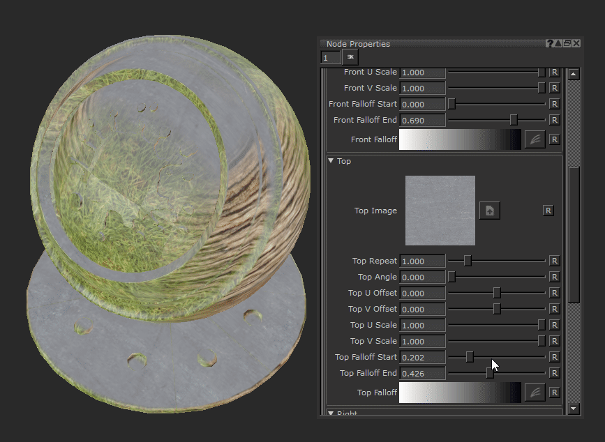
Top Falloff Curve editor |
This curve editor gives control of the falloff of the front projection. By manipulating the curve you can make the falloff harsher. This may be useful when texturing hard surface assets to avoid soft and blended textures. |


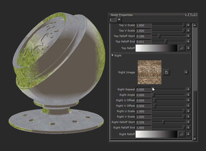
Right
|
Right Image image |
Chooses the image to project across the right of your geometry. |
||||||
|
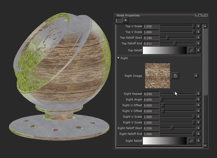
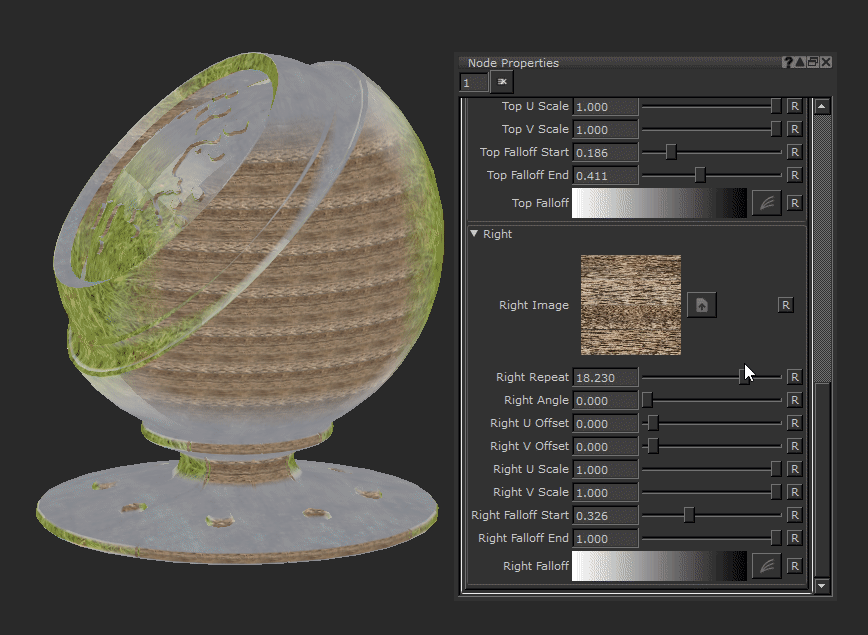
Right Repeat Text field, slider |
Changes the tiling amount of your projected image. Upping this value makes the image scale down.
Default is 0. |
||||||
|
Right Angle Text field, slider |
Changes the rotation of the projected image.
Default is 0. |
||||||
|
Right U Offset Text field, slider |
Moves the tiled image horizontally along the U axis of the projection.
Default is 0. |
||||||
|
Right V Offset Text field, slider |
Moves the tiled image vertically along the V axis of the projection.
Default is 0. |
||||||
|
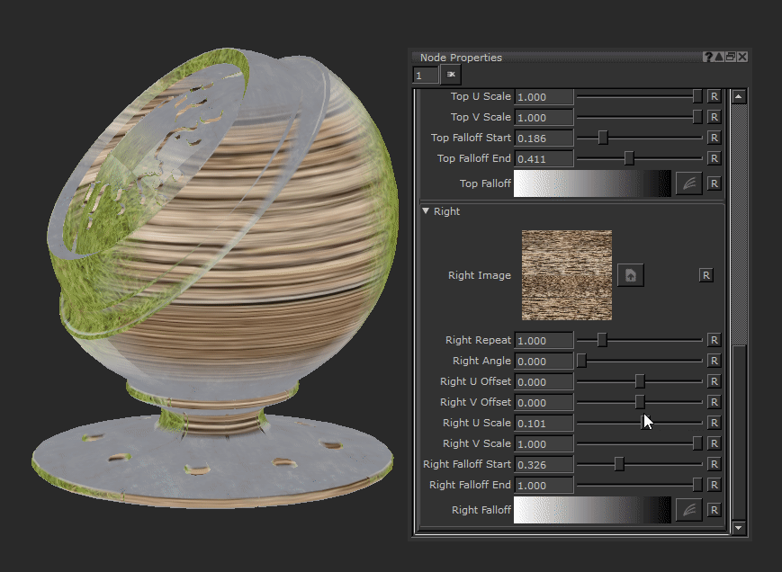
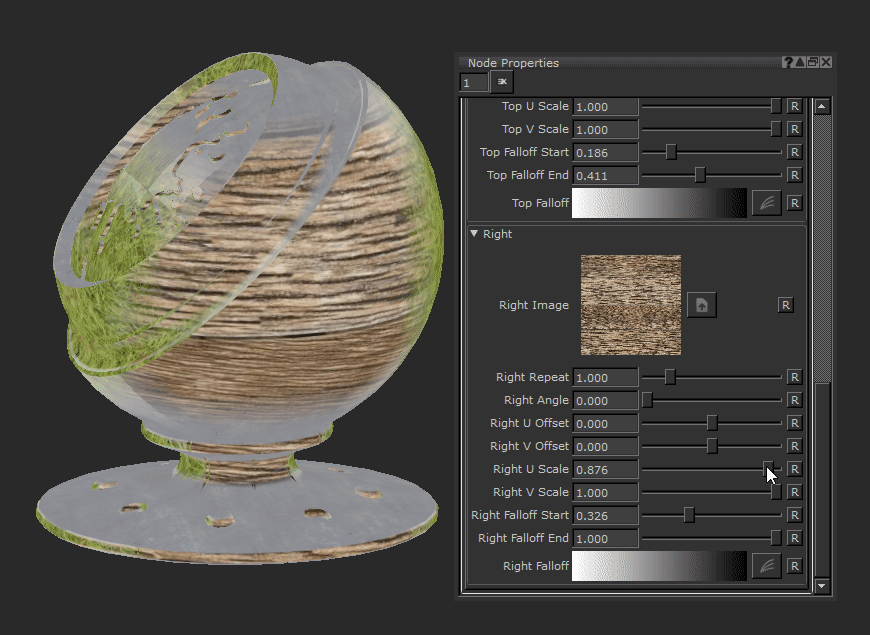
Right U Scale Text field, slider |
Scales the tiled image horizontally along the U axis of the projection. If this number is higher than the V Scale the image starts to elongate vertically.
Default is 1. |
||||||
|
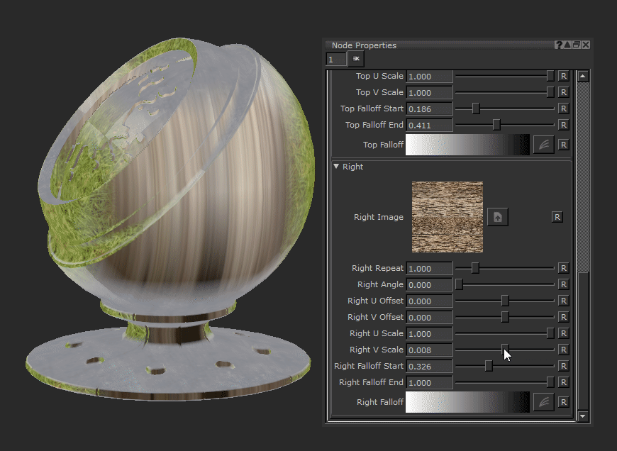
Right V Scale Text field, slider |
Scales the tiled image vertically along the V axis of the projection. If this number is higher than the U Scale the image starts to elongate horizontally .
Default is 1. |
||||||
|
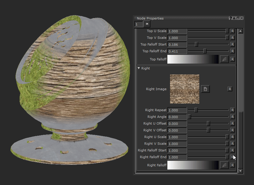
Right Falloff Start Text field, slider |
Changes the fall off of the right projection and the threshold at which angles the projection will cover. Raising this slider makes the projection cover more area on curved or glancing angles and may eventually overlap the other axes projections.
Default is 0. |
||||||
|
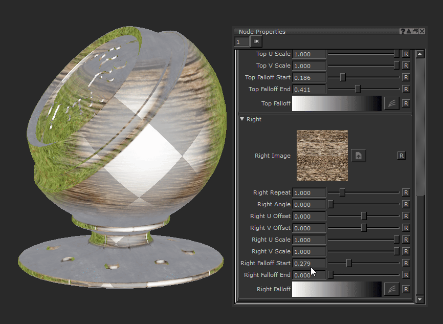
Right Falloff End Text field, slider |
Changes the fall off of the right projection and the threshold at which angles the projection covers. Lowering this slider makes the projection cover less area on curved or glancing angles.
Default is 1. |
||||||
|
Right Falloff Curve editor |
This curve editor gives control of the falloff of the front projection. By manipulating the curve you can make the falloff harsher. This may be useful when texturing hard surface assets to avoid soft and blended textures. |


Triplanar Projection Node Workflow Example
Hard Surface Texturing with the Triplanar Projection vs a Tiled Node
You can use the Triplanar Projection node to help with hard surface texturing. Since it doesn’t rely on UVs then you won’t get any texture stretching due to poorly laid out UVs.
This basic rectangular wall object will be our geometry for this example. If we look at the UVs they are not ideal. They’ve had a quick automatic unwrap and they've been purposefully made worse by differing the scale of the shells and rotating some differently.
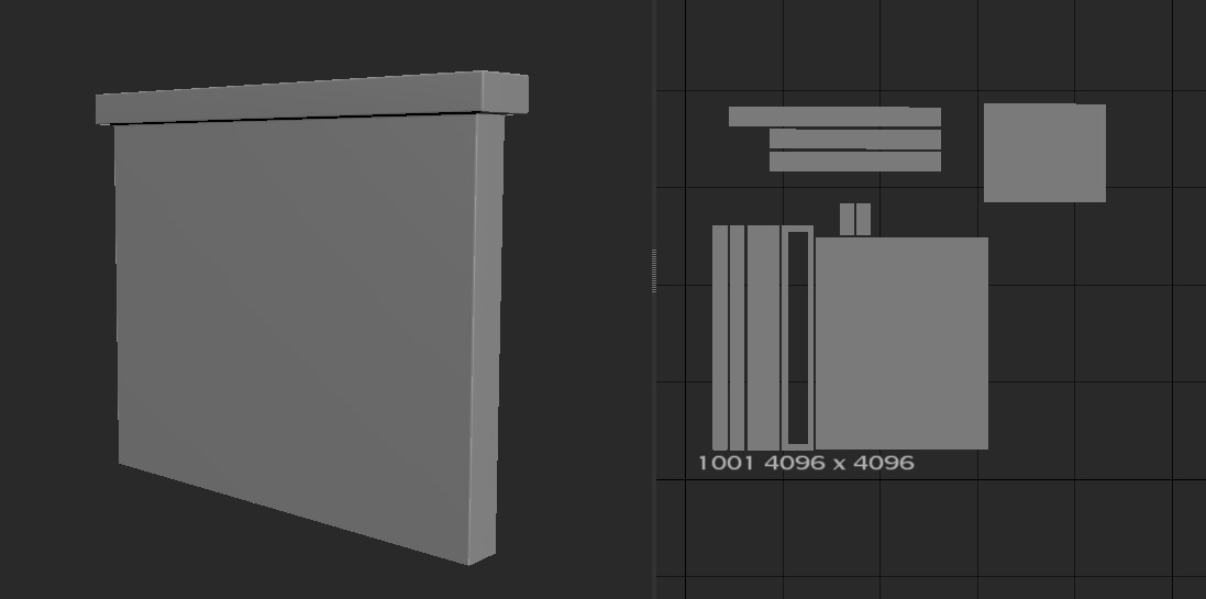
A basic wall model with bad UVs.
You may get less than ideal UVs when working with someone else. This would be an issue if you are working with the Tiled node, but the Triplanar node has no issue with it since it works in 3d Space.
The Tiled node is not working well with the bad UV layout.
Here with a Tiled Node using a brick texture we can see that having different scaled UVs and different rotation of the shells gives us bad results - we would need to use different Tiled Nodes with different properties masked off in different places to get it to work.
Lets use a Triplanar instead.

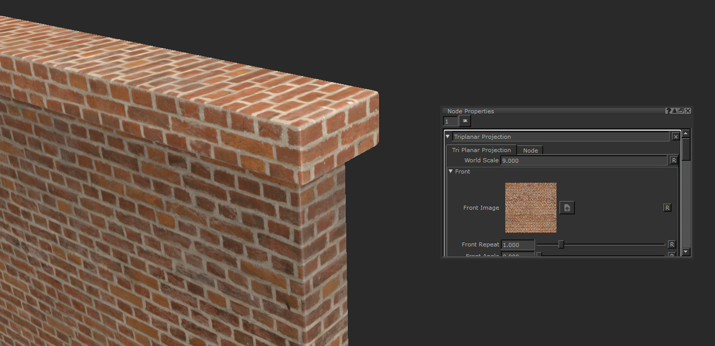
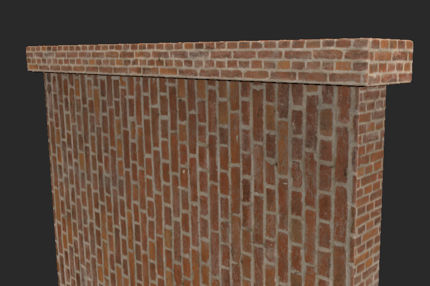
Triplanar handles the tiling much better.
After connecting that same image from our Image Manager into the Front, Top and Right image of the node, already you can see the difference. While the scale may be off the tiles all look consistent and at the edges they line up correctly, even with our poor UVs.
The world scale helps scale all the axis up equally.
Finally by changing the World Scale of the node, all the bricks have been sized up. This saves you having to change the Repeat value or the Scale Amount on each axis. This looks great and a perfect base to add some wear and dirt onto for this wall asset. Getting something similar with the Tiled node would have been difficult.
Bricks and tiles can be very temperamental when texturing as you need straight UVs, the same UV scale, and often your UV shells to be inline for the corners to match up correctly. Unlike other hard surface or organic materials it is very obvious when they are not right due to their high frequency and straight grid formation. The Triplanar node is a great help when your UVs are giving you trouble.
Related Nodes
Sorry you didn't find this helpful
Why wasn't this helpful? (check all that apply)
Thanks for your feedback.
If you can't find what you're looking for or you have a workflow question, please try Foundry Support.
If you have any thoughts on how we can improve our learning content, please email the Documentation team using the button below.
Thanks for taking time to give us feedback.