Search is based on keyword.
Ex: "Procedures"
Do not search with natural language
Ex: "How do I write a new procedure?"
Cellular Node
Access: Nodes > Procedural > Noise > Cellular
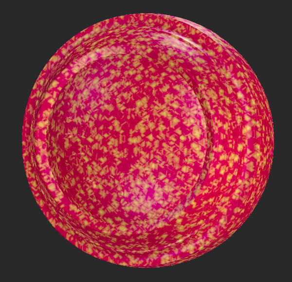
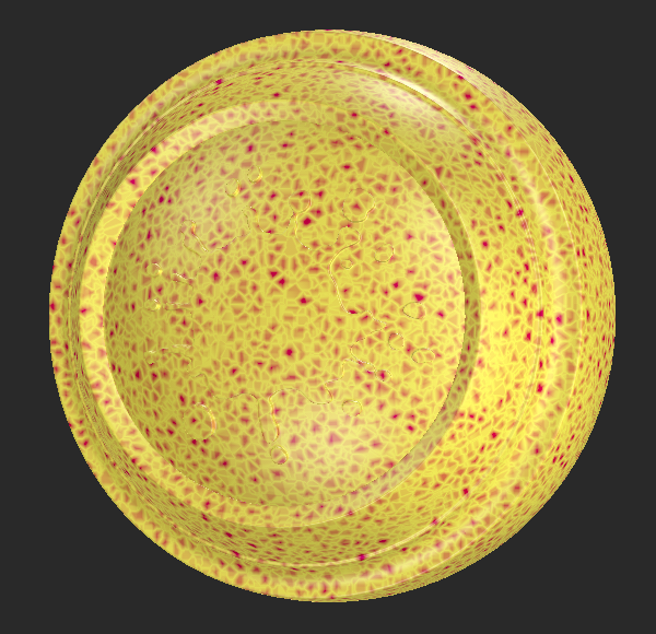
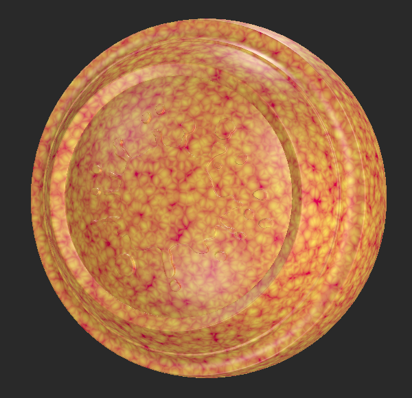
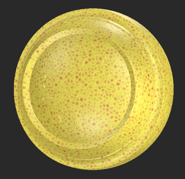
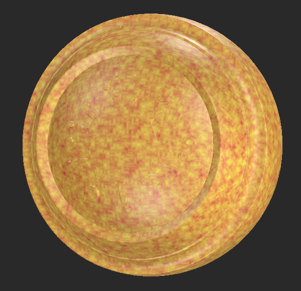
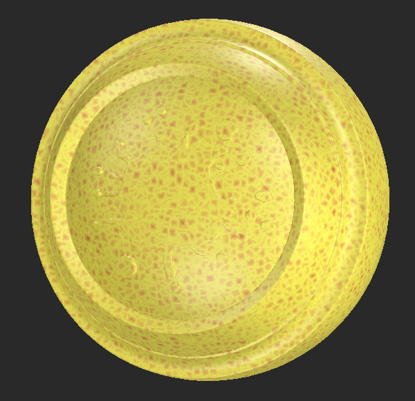
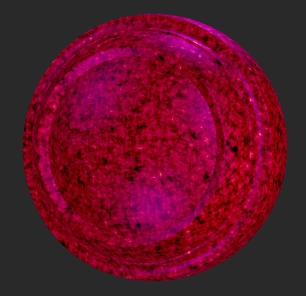
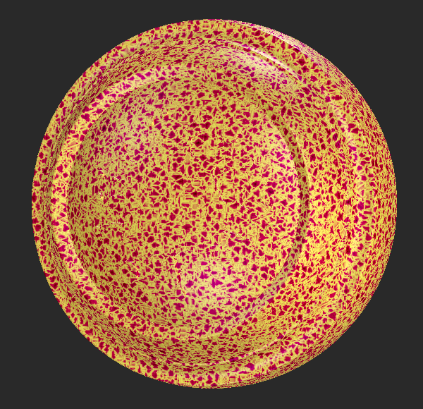
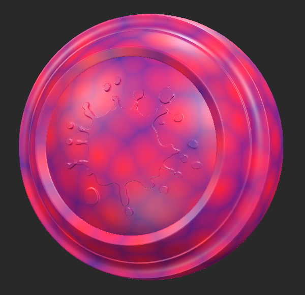
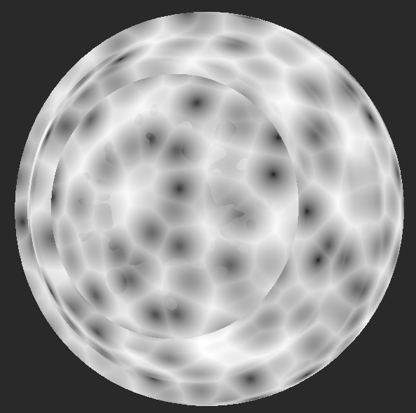
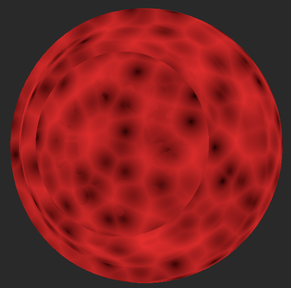
The Cellular node is a type of noise node that generates points randomly to simulate natural textures such as sparkles and gemstones, as well as organic textures such as human cells.
|
|
|
| Sparkles | Gemstones | Human Cells |
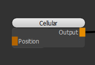
The Cellular node relies on 2D or 3D position information (set of numbers) on the canvas. Its Position input can be connected to any position nodes and you can adjust the position in various ways.
Tip: For example, you can use the UV and Position nodes to switch between 2D and 3D positions. You can also stretch the position using the Scale node or shift it using a Vector node.
Cellular Node Inputs
Position - Any position data can be connected to the Position input, such as the UV and Position nodes. You can use any type of node to modify the mapping of the pattern. For example, you can use the Scale or Vector node in conjunction with the Position or UV node to stretch or offset the position (data) from the Position or UV node.
Cellular Node Properties
The table below shows the type and distance method on the x and y axes.
| F1 | F2 | F2-F1 | |
| Manhattan | 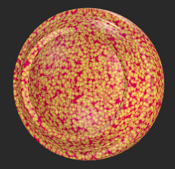
|
|
|
| Euclidian | 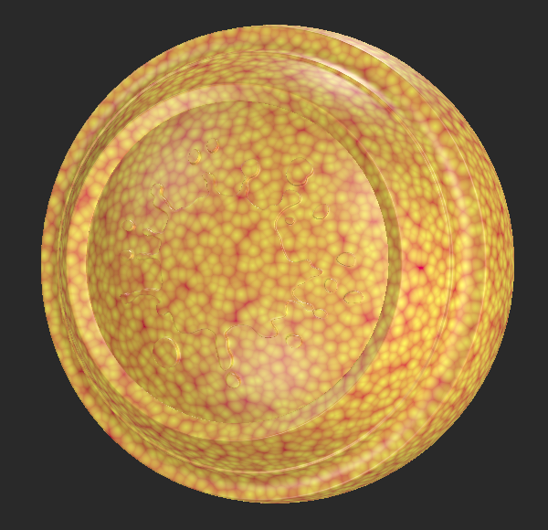
|
|
|
| Chebyshev | 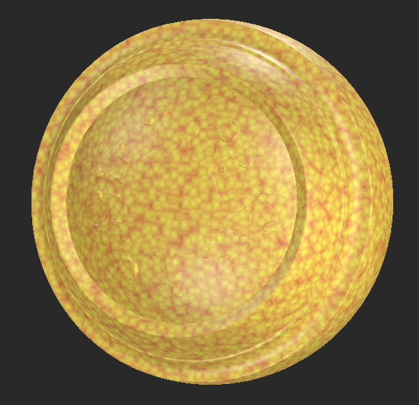
|
|
|
| 0.5 | 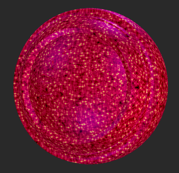
|
|
|
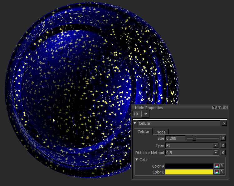
The Cellular noise node generates noise by computing distance to "feature points" scattered in the coordinate space.
|
Size floating point control |
Changes the size of the points driving the pattern.
|
||||
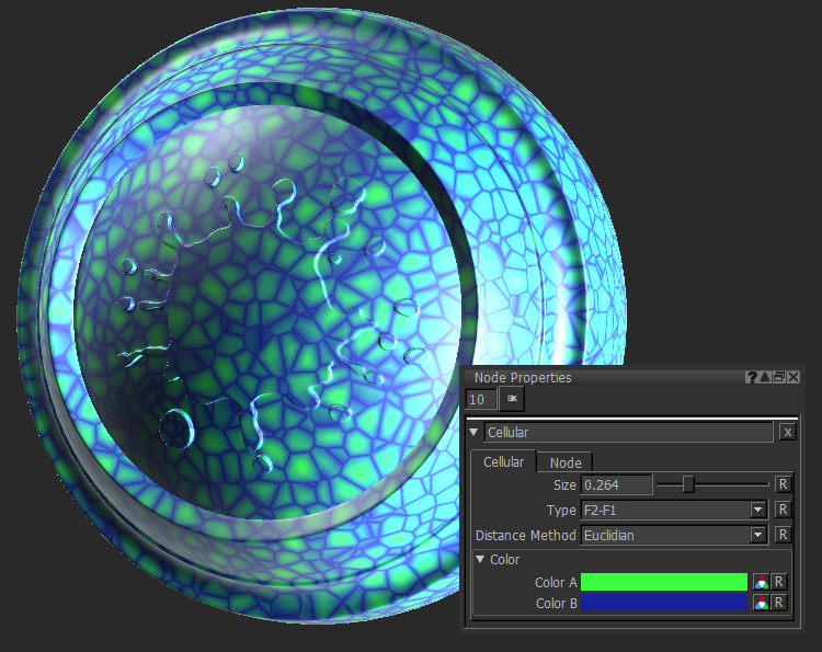
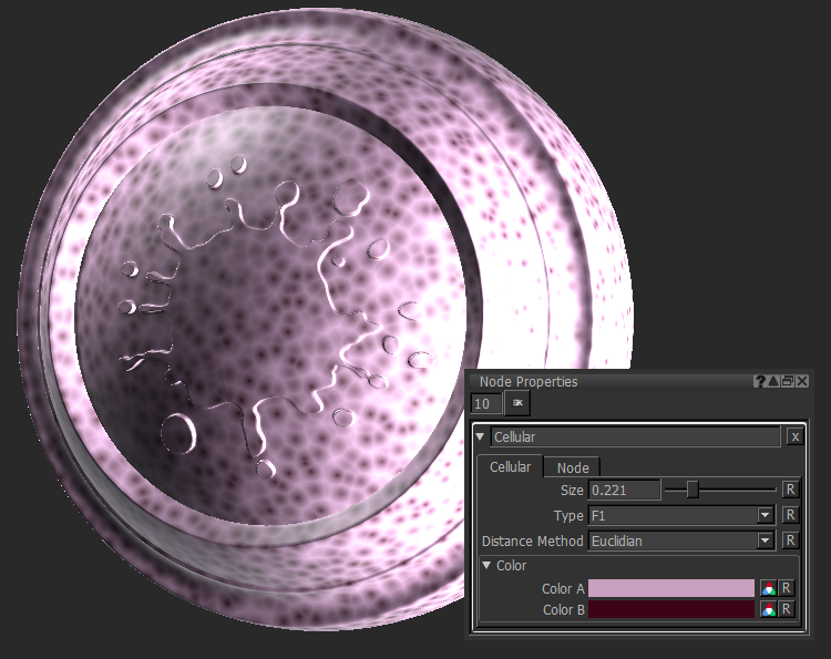
|
Type |
Changes how it computes the distance to render the noise: • F1 - computes the distance to the closest point. • F2 - computes the distance to the second closest point. • F2-F1 - computes the difference between the distances to the second closest point and the closest point. |
||||
|
Distance Method |
Changes the Distance Method used to render the noise: • Manhattan - Manhattan is a form of computing distance by taking the sum of distances in Cartesian coordinates. • Euclidian - Euclidian is a form of computing distance by the distance between two points in Euclidian space. • Chebyshev - Chebyshev is a form of computing distance by taking the longest distance in one dimension of coordinate space. • 0.5 - computes the distance by taking the p-norm where p is 0.5. |
Color
|
Color A
|
Changes the background color.
|
||||
| Color B
swatch |
Changes the color around the points.
|

Note: For more information on the Node tab in the Node Properties palette, see Node tab.
Cellular: Node Graph Workflow Examples
Example - Shifting the Mapping Position of the Cellular Node.
In the example below, let’s add a Vector node to the baseline position to shift the noise.
| 1. | Create a Cellular node. |
Adding a Cellular node to the scene.
| 2. | Create an Add node and connect it to the Cellular node. The Add node lets you use two nodes in conjunction to modify the output node, in this example, the Cellular node. Create a Vector node and a Position node and connect them respectively to the A and B inputs of the Add node. |
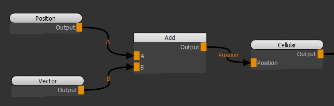
Adding a Position and Vector node to shift the position of the Cellular noise.
Notice how moving the X slider of the Vector node moves the noise on the X axis as we are changing the position information through the Position node.
Adjusting the position with the Vector node to shift the noise position.
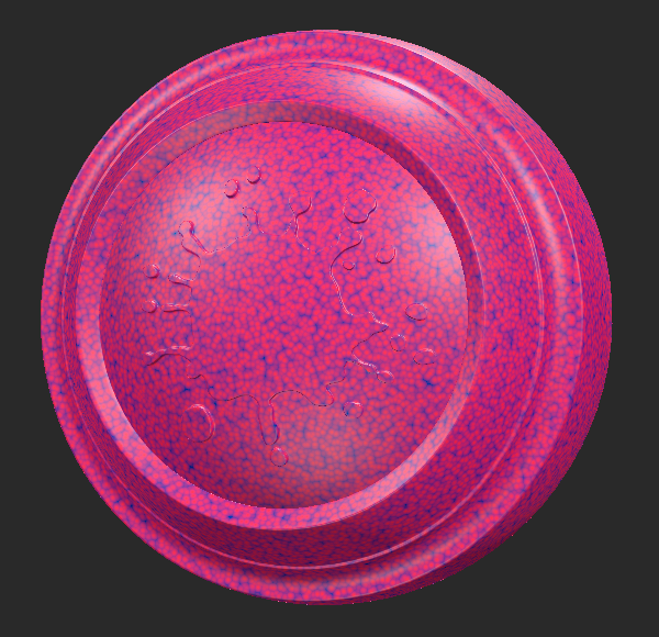
Example - Changing the Texture of the Cellular Noise.
In the example below, let’s add a Cloud node to the baseline position to change the texture of the Cellular noise.
| 1. | Create a Cellular node. |
Adding a Cellular node to the scene.
| 2. | Create an Add node and connect it to the Cellular node. Create a Cloud node and a Position node and connect them respectively to the A and B inputs of the Add node. |
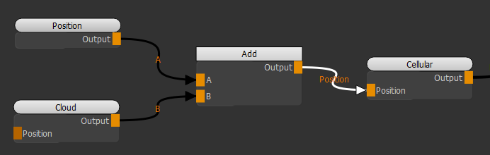
Adding a Position and Cloud node to distort the Cellular noise.
Notice how adjusting the Cloud node's foreground color (Color A) distorts the Cellular noise.
Changing the Cloud node's foreground color to distort the Cellular noise.
Related Nodes
• UV Node
Sorry you didn't find this helpful
Why wasn't this helpful? (check all that apply)
Thanks for your feedback.
If you can't find what you're looking for or you have a workflow question, please try Foundry Support.
If you have any thoughts on how we can improve our learning content, please email the Documentation team using the button below.
Thanks for taking time to give us feedback.