Search is based on keyword.
Ex: "Procedures"
Do not search with natural language
Ex: "How do I write a new procedure?"
Vector Node
Access: Nodes > Basic > Vector
Under the hood, Mari passes around a set of four numbers along a connection between two nodes. The Vector node is solely used as a set of four numbers (x, y, z, and w). You can use the Vector node in conjunction with nearly any node, depending on your workflow. For example, you can use it to adjust the position or color information, or you can use it as a number to change the value of another node, for instance, a shading node.
Vector Node Inputs
No input.
Vector Node Properties
|
X
|
First component of the vector. If applied to RGBA, this is the red component. |
|
Y
|
Second component of the vector. If applied to RGBA, this is the green component. |
|
Z
|
Third component of the vector. If applied to RGBA, this is the blue component. |
|
W
|
Fourth component of the vector. If applied to RGBA, this is the alpha component. |
Vector: Node Graph Workflow Example
Changing the Position of the Noise
In this example, let’s use a Vector node to change the position of the Wood procedural applied to the object.
| 1. | Create a Wood node. |
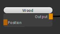
Adding a Wood node to texture the object.
| 2. | Create an Add node and connect it to the Position input of the Wood node. Create a Vector and a Position node and connect them respectively to the A and B inputs of the Add node. |
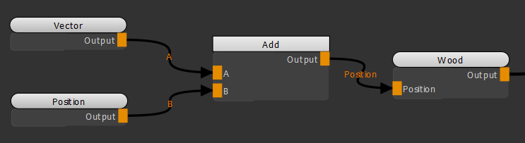
Adding a Vector node in conjunction with a Position node and an Add node to adjust the position of the Wood texture.
Notice how moving the X slider of the Vector node (see Vector Node Properties) moves the Wood texture on the X axis as the position information is changed.
Adjusting the position of the Wood texture by changing the X value of the Vector node.
Changing the Color of an Object
In this example, let's use a Vector node to change the color of the object.
| 1. | Create a Color node. |
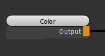
Original scene contains a Color node.
| 2. | Open the Color node's Node Properties and change the Color to blue. |
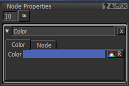
Color node's Node Properties
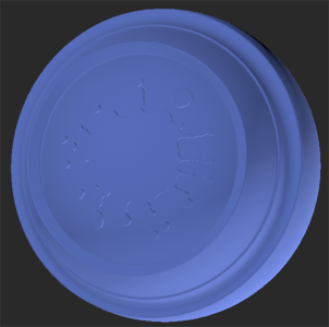
Color node applying a blue color to the object.
| 3. | Create an Add node. Create a Vector node and connect the Vector node and the Color node respectively to the A and B inputs of the Add node. |
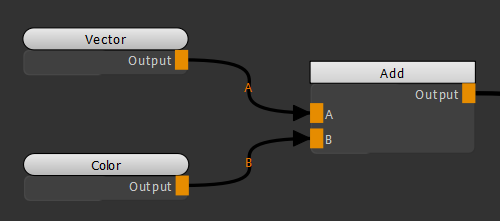
Adding a Vector node in conjunction with an Add node to change the color of the object.
Notice how moving the Y slider of the Vector node (see Vector Node Properties) changes the Green component of the Color node.
Changing the Green component of the Color node by adjusting the Y value of the Vector node.
Using the Vector Node as a Number
In this example, let's use a Vector node to make changes to the Roughness channel of the Principled BRDF shader.
| 1. | Create a Tiled node and a Principled BRDF node. Connect the Tiled node to the Base Color input of the Principled BRDF shader. |
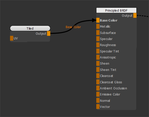
Connecting a Tiled node to the Principled BRDF node.
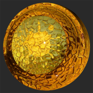
This is the visual output of the texture applied using the Tiled node.
| 2. | Create a Vector node and connect it to the Roughness input of the Principled BRDF. |
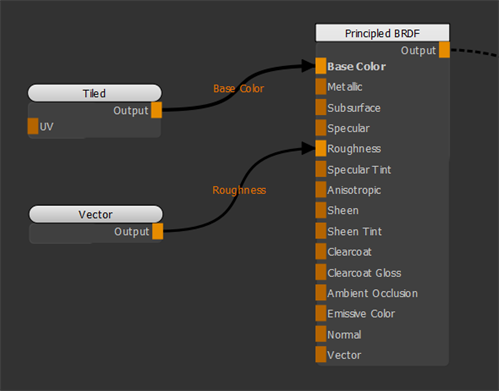
Adding a Vector node and connecting it to the Roughness input of the Principled BRDF shader.
Notice how moving the X slider of the Vector node (see Vector Node Properties) changes the Roughness of the surface.
In this example, the Vector node is used as a number.
Changing the Roughness of the surface by changing the X value of the Vector node.
Related Nodes
Sorry you didn't find this helpful
Why wasn't this helpful? (check all that apply)
Thanks for your feedback.
If you can't find what you're looking for or you have a workflow question, please try Foundry Support.
If you have any thoughts on how we can improve our learning content, please email the Documentation team using the button below.
Thanks for taking time to give us feedback.