Search is based on keyword.
Ex: "Procedures"
Do not search with natural language
Ex: "How do I write a new procedure?"
Turbulence Node
Access: Nodes > Procedural > Fractal > Turbulence
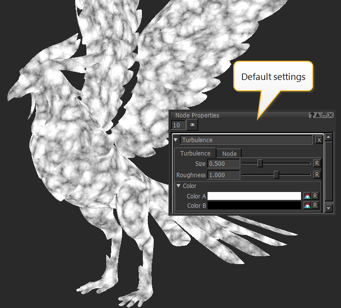
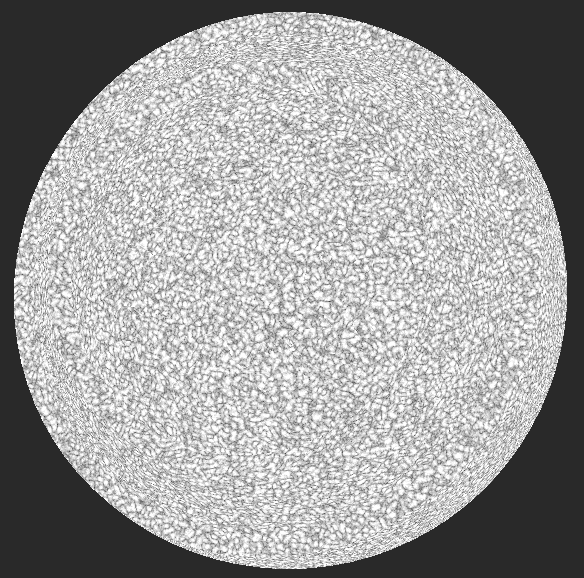
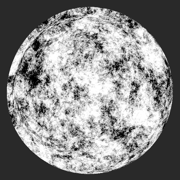
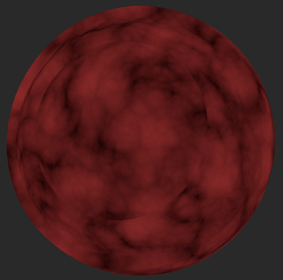
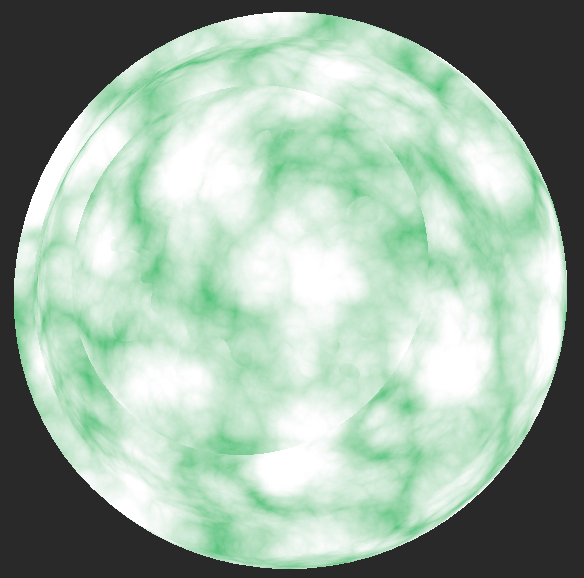
The Turbulence node is a type of noise node that generates random patterns to simulate stormy cloud-like textures.
|
|
|
|
|
Turbulence node's default settings |
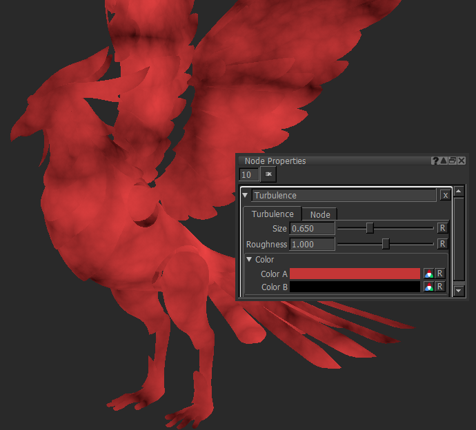
Turbulence node's Size increased, |
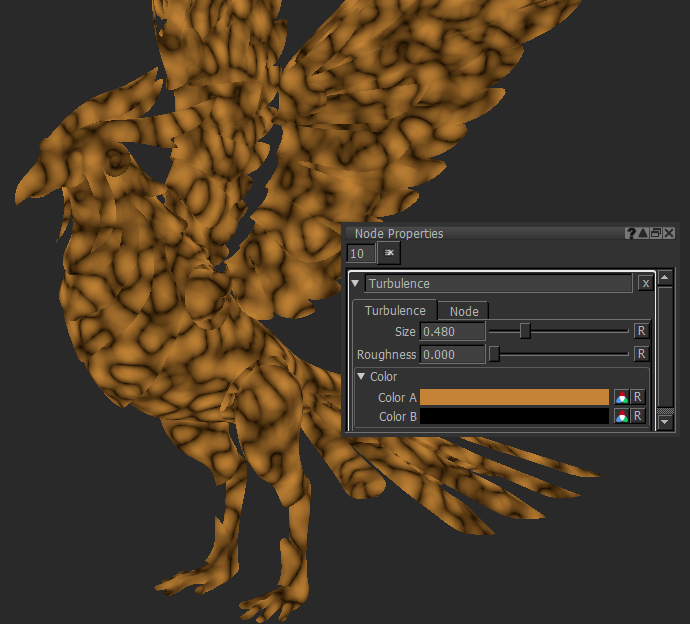
Turbulence node's Size decreased, |
The Turbulence node relies on 2D or 3D position information (data) on the object. Its Position input can be connected to any position nodes and you can adjust the position in various ways.
Turbulence Node Inputs
Position - Any position data can be connected to the Position input, such as the UV and Position nodes. You can use any type of node to modify the mapping of the pattern. For example, you can use the Scale or Vector node in conjunction with the Position or UV node to stretch or offset the position (data) from the Position or UV node.
Turbulence Node Properties
|
Size
|
Changes the size of the noise.
|
||||
|
Roughness
|
Changes the roughness appearance of the noise, from very smooth at low values to very rough.
|
Color
|
Color A
|
Changes the background color.
|
||||
|
Color B
|
Changes the color around the stormy cloud-like pattern.
|
Turbulence: Node Graph Workflow Examples
Example - Obtaining a Blended Texture Using a Turbulence node
In this example, let’s use the Turbulence node as a mask on top of two different textures (Tiled 1 and Tiled 2) to obtain a nice blended texture.
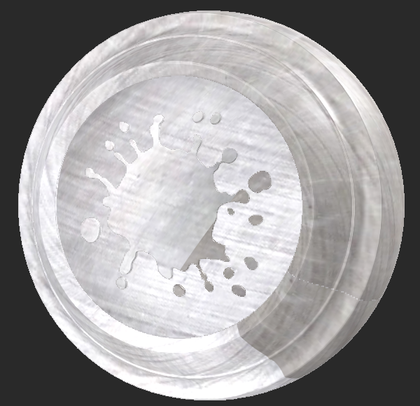
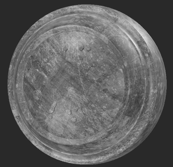
These are the visual outputs of Tiled 1 and Tiled 2.
|
|
|
|
Texture 1 is hidden under Texture 2. |
Texture 2 is visible. |
| 1. | Create two Tiled nodes and connect them to the Base and Over input of the Merge node. |
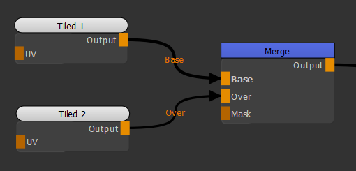
Adding two Tiled nodes to the Merge node to achieve a layering operation.
| 2. | Connect a Turbulence node to the Mask input of the Merge node. |
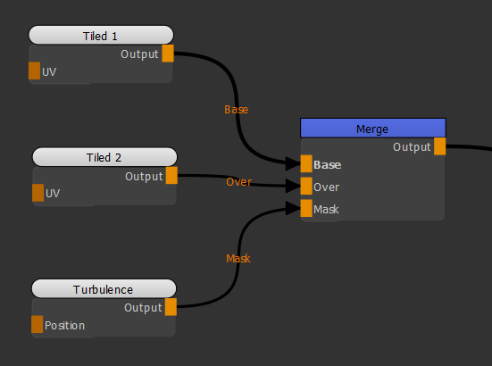
Adding a Turbulence node the scene as a mask to blend Tiled 1 and Tiled 2 together.
Notice how Texture 1 and Texture 2 are both made visible due to the Turbulence node applied as a mask.
Texture 1 and Texture 2 are both made visible due to the Turbulence node applied as a mask.
Example - Switching Mapping from 3D space to UV space
In this example, let’s use a UV node to adjust the Turbulence noise from 3D space to UV space.
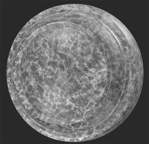
| 1. | Create a Turbulence node. |
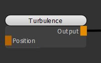
Adding a Turbulence node to the scene.
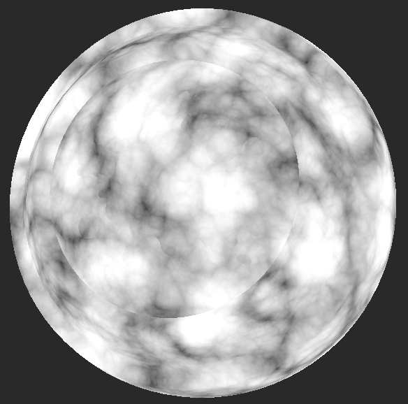
The Turbulence node is represented in 3D space. Notice that this method doesn't contain UV seams.
Turbulence node represented in 3D space.
| 2. | Create a UV node and connect it to the Position input of the Turbulence node. |
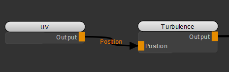
Adding a UV node to the scene by connecting it to the Turbulence node.
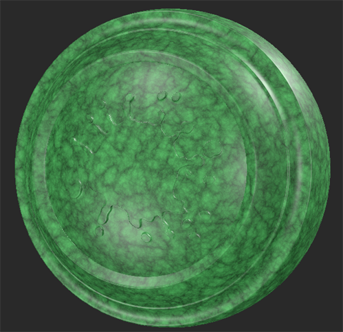
The Turbulence noise is now represented in 2D space.
Notice the UV seam on the right-hand side of the model, which shows the border of a patch.
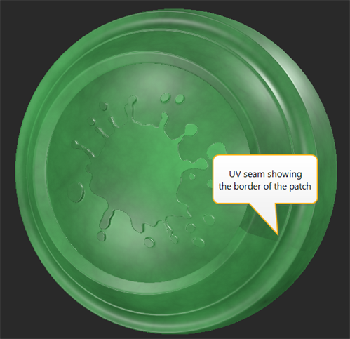
Turbulence node represented in 2D space.
The following image is the UV view of the model to give you a better idea of the noise layout.
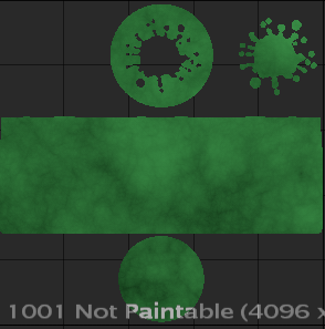
UV view of the model.
Related Nodes
• UV Node
• Scale node
Sorry you didn't find this helpful
Why wasn't this helpful? (check all that apply)
Thanks for your feedback.
If you can't find what you're looking for or you have a workflow question, please try Foundry Support.
If you have any thoughts on how we can improve our learning content, please email the Documentation team using the button below.
Thanks for taking time to give us feedback.