Teleport Broadcaster and Teleport Receiver Nodes
Access: Nodes > Misc > Teleport Broadcaster or Teleport Receiver
The Teleport nodes are designed to help declutter your node graph by transmitting data across hidden connections. Any node can be plugged into the Input of a Teleport Broadcaster which is then transmitted to one or more Teleport Receiver nodes, even from within nested groups and materials.
As of Mari 7, The Teleport Broadcaster includes an output, so that in addition to the broadcast, you have the option to chain the node in the usual way as part of the node graph data flow.
Tip: A broadcast can be made to multiple receivers, but a receiver can only listen to one broadcast.
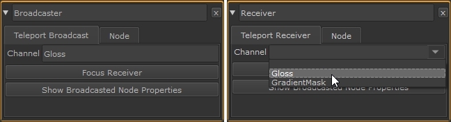
To create a connection between a Teleport Broadcaster and a Teleport Receiver node, just use the same Channel name in both nodes. You can enter a name into the Channel control in the node Properties manually or select an existing Channel from the dropdown in the receiver's Properties.
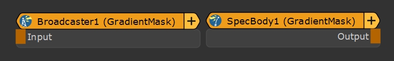
The broadcast and received Channel name is displayed on the nodes in brackets, (Gloss) in the example.
Tip: You can change the node color of broadcasters and receivers in the Preferences under Node Graph > Node Category Colors > Teleport.
Teleport Broadcast Node Properties
|
Channel text field |
Enter the Channel name broadcast from this node to Teleport Receivers in the node graph. The name can be anything, but it's good practice to use a descriptive name so that you can quickly pick the correct broadcast in the receiver. |
|
Focus Receiver button |
Click to display a list of receivers with the Channel control set to this broadcast. Select the required receiver to center the node graph on the chosen Teleport Receiver node. |
|
Show Broadcasted Node Properties button |
Click to quickly display the Properties of the node connected to the Teleport Broadcaster node's input. |
Teleport Receiver Node Properties
|
Channel text field, dropdown |
Enter the Channel name to receive from a Teleport Broadcaster node in the node graph or use the dropdown to choose from the available broadcasts. |
|
Focus Connected Broadcaster button |
Click to center the node graph on the Teleport Broadcaster node transmitting the Channel this node is receiving. |
|
Show Broadcasted Node Properties button |
Click to quickly display the Properties of the node connected to the Teleport Broadcaster node's input. |
Teleport Broadcaster and Teleport Receiver Nodes Workflow Example
Broadcast a Mask to Multiple Node Graph Locations
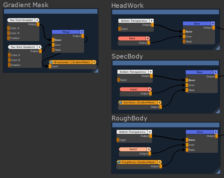
In this simple example, we'll reuse a gradient mask in specular and roughness operations without cluttering up the node graph with Dot nodes and connectors. The image shows the Gradient Mask connected up to the Mask inputs of two Merge nodes using standard Mari connections.
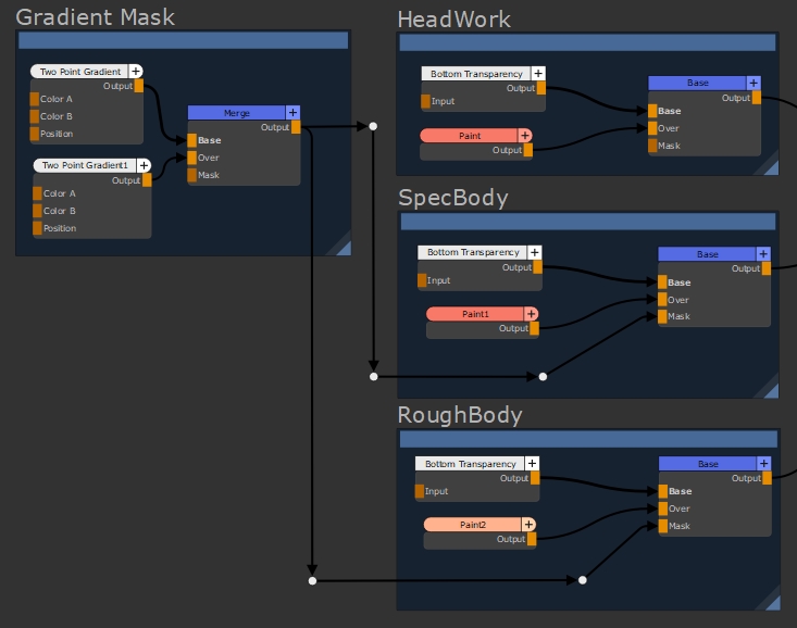
To tidy up the node graph, let's replace the connecting pipes and Dot nodes by broadcasting the mask and then receiving the data closer to the Mask inputs.
- Press Tab in the node graph, type Teleport, and then select Teleport Broadcaster.
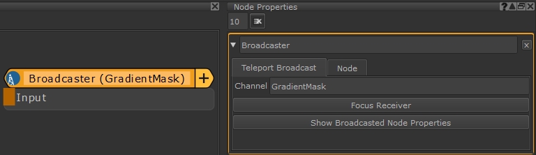
- Double-click the node to open its Properties panel.
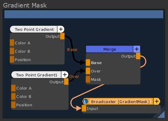
- In the Channel control, enter the name of the broadcast. Let's call the broadcast GradientMask.
The name can be anything, but it's good practice to use a descriptive name so that you can quickly pick the correct broadcast in the receiver. - Connect the Gradient Mask Output to the broadcaster.
- Press Tab in the node graph, type Teleport, and then select Teleport Receiver.
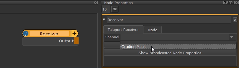
- Double-click the node to open its Properties panel.
- In the Channel control, click the dropdown and select the broadcast GradientMask.
- Connect the receivers to the Mask inputs of the required nodes to complete the clean-up.
Tip: You can type the Channel name manually if you prefer.
You can change the name of the receiver for clarity in the node graph. For example, you could name this receiver SpecBody and create another receiver called RoughBody to differentiate between the two.
Tip: You can also change the node color of broadcasters and receivers in the Preferences under Node Graph > Node Category Colors > Teleport.
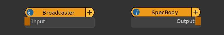
You can see in the node graph when broadcasters and receivers are working correctly because the blue icon on the left-hand side of the nodes changes to indicate a signal.
|
|
|
A disabled broadcast pair |
|
|
|
An enabled broadcast pair |