Curve Slice

The Curve Slice tool cuts the mesh with a user-defined curve. There are two methods possible:
| 1. | Create a curve and place it in the background. |
Note: Make it visible in the Item List, but do not select it.
When you activate the tool, the background curve becomes the cutting source.
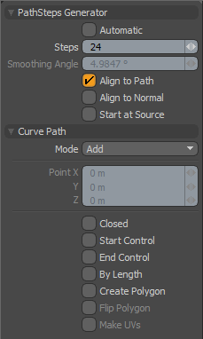
| 2. | If there is no visible background curve when you activate the tool, draw a slicing curve interactively in the 3D viewport and then edit it as you would with a normal curve. (See the Curve tool topic for information about editing curves.) The Path Steps Generator section of this tool's Properties panel has settings to control the number of steps along the curve, which affects the smoothness of the newly created edges. |
Procedural Curve Slice
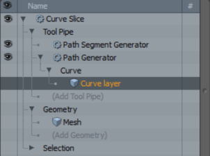
Curve Slice is also available as a procedural mesh operation. It is a combination of the Slice Effector, Path Segment Generator, and Path Generator sub-tools. You can add the tool from the Mesh Ops tab, on the right-side of the Model layout.
To use the tool, you need a geometry to cut and a slicing curve to cut with.
| 1. | Add the geometry you want to slice using the Add Operator button in the Mesh Ops tab. |
| 2. | Add a new mesh layer to place the curve in: Click Add Item in the upper half of the Mesh Ops tab and select Item > Mesh. |
| 3. | With the new mesh layer selected, draw a curve in it, using the traditional curve tools in Curve tab of the modeling toolbox. For more information, see Curve. |
| 4. | Select your original mesh layer, the one that contains your geometry, and in the Mesh Ops tab, click Add Operator, then select Mesh Operations > Edit > Curve Slice. |
The Create Slice Clone dialog opens.
| 5. | Select the mesh that contains your curve as Path, then click OK. |
Curve Slice is added to the Mesh Operations list. When you expand it by clicking the small arrow in front of it, you can see its inputs.

Tip: To improve your modeling workflow, use the procedural modeling Delete operation. For more information, see Edit Commands - Delete/Remove.
You can also use the Select by Previous Operation mesh operation. The following Name options is available for the Curve Slice tool: Intersecting Edges. For more information, see Select by Previous Operation.
Curve Slice Properties
The following options are available:
|
Option |
Description |
|
Enable |
Activates/Deactivates tool. By default, this property is enabled. |
|
Use World Transform: |
Centers a geometry selection at the World Origin position. By default this property is enabled. |
|
Axis |
Defines the axis across which to project the drill function. |
|
Vector X, Y, Z |
Sets the axis vector position for X, Y, and Z. |
|
Select Sliced Edges |
Sets edge selections for sliced edges to the selection set. The selection is automatically created and displayed in the Mesh Ops tab under Lists. |
|
Edge Selection Set |
Defines the name of the edge selection set for the Select Sliced Edges option. This name can be entered in the Add Operator > Mesh Operations > Selection > Select By Selection Set which can be used with Edge mesh operations. |