Search is based on keyword.
Ex: "Procedures"
Do not search with natural language
Ex: "How do I write a new procedure?"
Channel Modifiers
Channel Noise
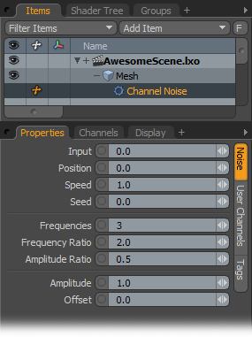
This motion generator creates a smoothly changing random value by taking a one-dimensional slice through a 3-dimensional fractal noise field.
• Input: This is the x-coordinate for the slice.
• Position: This is the y-coordinate for the slice.
• Speed: This indicates a scale time for the z-coordinate for the slice.
• Seed: This provides a random start time to move the z-coordinate.
• Frequencies: Indicates the number of octaves of noise to add together.
• Frequency Ratio: Determines the ratio of frequencies of successive octaves.
• Amplitude Ratio: Determines the ratio of amplitudes of successive octaves.
• Amplitude: This is a scaling factor for Modo to apply to the output.
• Offset: This specifies a value for Modo to add to the output.
Channel Oscillator
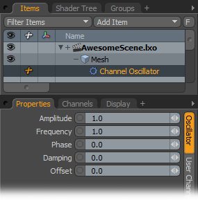
This modifier can be considered more of a motion generator because it generates a standard sine wave. When applied to a channel, this modifier creates smoothly undulating values. For a more random effect, use a Channel Noise generator.
• Amplitude: This indicates the size of base waveform without damping. The channel ranges from -Amplitude value to +Amplitude value.
• Frequency: Determines the frequency of sine wave in cycles per second (Hz).
• Phase: Specifies a phase shift for the sine wave as a percent of a wavelength/cycle (for example, 90 deg shift = 90/360 = 25%).
• Damping: Indicates a reduction of the sine wave expressed as fraction of amplitude lost per cycle.
• Offset: This specifies a DC value for Modo to add to the sine wave. The output value then ranges from Offset - Amplitude to Offset + Amplitude.
Channel Relationship
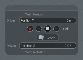
This modifier defines a non-linear relationship between two values that can be modified visually with a Graph curve. Using this modifier is unlike a standard direct link where, once applied, modifying the incoming channel instantly affects the outgoing channel. With this modifier, once you link the items, you must define the relationship itself numerically in the Relationship interface window in the 3D viewport. This window only appears when you select the Channel Relationship item, itself.
You define the relationships with the buttons in the window. Modo gives the two channels as Driver and Driven, which means that the values of one output (Driver) control the input of another (Driven). The square white button sets a relationship key based on the current Driver and Driven values. Click the arrows to jump between keys. The red x deletes the current key. Click the Graph button to open the Graph Editor refine the curve.
The videos demonstrate the use and application of the Relationship Modifier.
Relationship Basics:
Firehose Demonstration:
Sorry you didn't find this helpful
Why wasn't this helpful? (check all that apply)
Thanks for your feedback.
If you can't find what you're looking for or you have a workflow question, please try Foundry Support.
If you have any thoughts on how we can improve our learning content, please email the Documentation team using the button below.
Thanks for taking time to give us feedback.