Search is based on keyword.
Ex: "Procedures"
Do not search with natural language
Ex: "How do I write a new procedure?"
Planar IK
Inverse Kinematics (IK) is a method of animating items in which software calculates the bending of a joint based on the position of a goal object. In Modo, the goal object is usually a locator. Once you have set up IK for a series of items, the IK hierarchy causes the item to continually reach for the goal when the goal item moves around and modifies the joint rotations as necessary.
With IK, it is much easier to animate the position of one item (the goal) than to animate the rotations of several separate items. For example, to animate a hand on a doorknob with IK, the goal can be positioned at the door knob and the hand is in the proper place in the scene. With a standard hierarchy, both the shoulder and the elbow must be rotated independently to find the correct position for the hand.
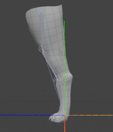
Modo's Planar IK system works well for dual joints, such as the arm mentioned in the previous example, but also allows you to animate three locator joints, for instance an animal's leg.
Note: You may also consider the more powerful Full Body IK system, which allows you to rig an entire character.
Applying IK to a Chain of Locators
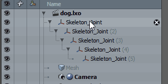
To apply IK to a chain of items, first create the hierarchy:
• Parent the items to each other in a descending chain.
• Make sure the Center positions are in the proper location as well. For Modo to calculate the IK correctly, all Center positions must share at least one axis value to appear in the same plane.
• Make sure the chain has a bend to it so that when Modo applies the IK, it can use a preferred angle for bending.
Tip: Enable Overlay Drawing in the 3D viewport to make the joints visible within the mesh.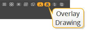
| 1. | Once the items are in order, select the items in descending order. |
| 2. | Enter Setup mode by clicking the Setup mode |
A yellow frame appears around the 3D viewport, indicating that you're in Setup mode.
Note: For more information on using Setup mode, see Binding and Setup Mode.
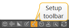
| 3. | In the Setup toolbar, go to the Inverse Kinematics tab and under Planar IK, click the Apply IK button. |
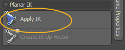
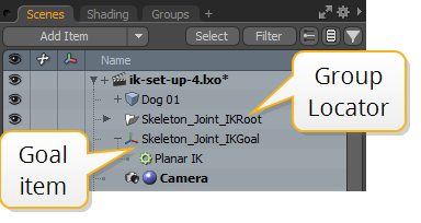
Applying the IK modifier to the chain creates a goal item and adds a group locator as the overall parent for the IK chain.
Note: A warning is displayed if your joints don't share an axis. Click OK to align your items along the X axis.
| 4. | Exit Setup mode. |
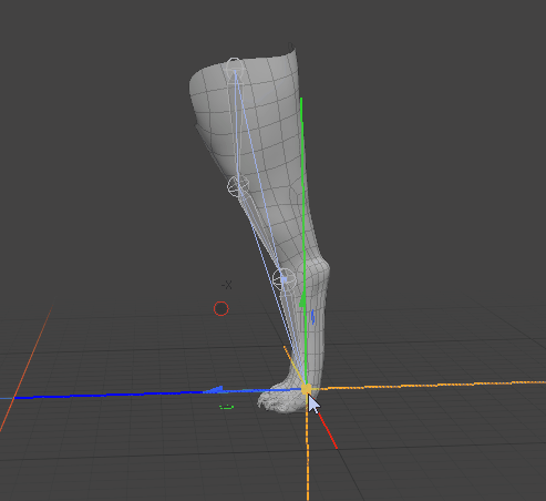
By moving the goal item, Modo modifies the angle of the joints in the IK chain.
Matching FK to the Current IK Position
When you move the goal item and want Forward Kinematics (FK) to match its position, you can set FK to use the current IK position.
| 1. | Select the goal locator (called Skeleton_Joint_IKGoal by default) in the Item List and move it to the required position. |
| 2. | When the goal item is selected, the Planar IK properties open in the Properties tab. Click the Set FK to Current button. |
| 3. | Disable IK by setting Blend to 0%. |
The joint chain's starting position moves to the new position.
Matching IK to FK
You can reset your chain to the starting position using the Reset Solver from IK button in the Properties. This allows you to go back to editing the individual joints, for instance.
| 1. | Select the goal item in the Item List and go to the Properties tab on the lower right. |
| 2. | Click the Reset Solver from IK button. |
The IK solver and joint chain are reset to the starting position.
Planar IK Properties
Selecting the goal item in the Item List displays the properties related to the IK chain.
|
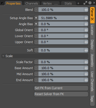
Blend |
A setting of 100% fully uses the IK solution. Values below 100% reduce the effect of IK on the chain, and a setting of 0% disables it. |
|
Setup Angle Bias |
Specifies the resting state for the chain. This setting should be adjusted in Setup mode to give a default behavior for the joints in the chain. |
|
Angle Bias |
Controls the weighting of the joints towards the start or end of the chain. After leaving Setup mode, you can adjust or keyframe the Angle Bias option to alter the behavior of the chain for a specific animation. This amount is added to the Setup Angle Bias. So if you have a Setup Angle Bias of 50% and an Angle Bias of 10%, the overall bias used for the joint angles is 60%. The separate controls allow you to adjust the chain in Setup mode without having to redo any changes made to the bias in animations. Note: Angle Bias is available for three-joint chains only. |
|
Global Orient |
Specifies the planar orientation angle of the IK chain. For example, for an arm, you can adjust the angle the elbow points toward. |
|
Lower Orient |
Specifies the planar orientation angle of the lower two joints of a three-joint chain. Note: Lower Orient is available for three-joint chains only. |
|
Upper Orient |
Specifies the planar orientation angle of the upper two joints of a three-joint chain. Note: Upper Orient is available for three-joint chains only. |
|
Soft |
When overextending a joint, it snaps to the goal position by default. Increasing this value removes the snapping and produces a slower transition. |
|
Scale |
|
|
Scale Factor |
When the goal point is too far from the sum of the joint lengths, the IK solver can scale the joints to match the goal position. 0% means no scaling, while at 100%, the joints are fully scaled. The Base, Mid, and End Amount settings allow you to determine the distribution of the scale amount across the joints. |
|
Base Amount |
Scales only the first joint. |
|
Mid Amount |
Scales only the middle joint. |
|
End Amount |
Scales only the last joint. |
|
Set FK from Current |
Matches FK to the current position of the IK. For more information on how to do this, see Matching FK to the Current IK Position. |
|
Reset Solver from FK |
Removes IK from the chain and allows you to edit the joints individually. For more information on how to do this, see Matching IK to FK. |
Create IK Up Vector
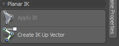
This vector defines the up direction for an IK constraint and can help to keep the chain oriented properly during animation. The Create IK Up Vector button is similar to the Assign Up Vector command except you don't need to create and position a locator. With Create IK Up Vector, Modo generates the locator automatically based on the preferred bending angle. Once the new Up Vector locator is available, you can animate it to adjust the orientation of the IK rig. This is similar to adjusting the Global Orient setting in the IK Properties panel. You can also combine IK Up Vector with Global Orient to produce any required orientation.
Sorry you didn't find this helpful
Why wasn't this helpful? (check all that apply)
Thanks for your feedback.
If you can't find what you're looking for or you have a workflow question, please try Foundry Support.
If you have any thoughts on how we can improve our learning content, please email the Documentation team using the button below.
Thanks for taking time to give us feedback.