Search is based on keyword.
Ex: "Procedures"
Do not search with natural language
Ex: "How do I write a new procedure?"
Using Curves with MeshFusion
Curves, Beziers, and B-Splines can serve as input meshes in MeshFusion modeling. They can be used the same way as regular polygonal meshes and produce primaries, trims, and surface strips.
B-Splines are native to MeshFusion, but Curves and Beziers are automatically converted to B-Splines when used by MeshFusion. Bezier curves can only be converted to B-Spline approximately, but you can increase the number of B-Spline segments for greater accuracy.
MeshFusion works with open, closed, flat, and 3D curves. You can also use curves produced by the Text tool with the Bezier Output Type.
Using a Curve as an Input Mesh
To use a Curve as an input mesh, make sure you have a scene containing a mesh item in one layer and a curve in another mesh layer.
Note: For more information on adding different types of curves, see Adding Curves, Bezier, or B-Spline.
| 1. | Select your mesh item in the Item List, and create a new fusion item, as described in Creating a New Fusion Item. |
Your mesh item becomes a primary and it's marked with green in the Item List and the 3D viewport. A Fusion Item is also created.
| 2. | In the Item List, select the mesh layer containing your curve, and the mesh layer containing your primary. |
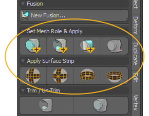
| 3. | In the Fusion sub-tab on the left panel, click the required button, depending on the kind of trim or surface strip you want to create. For example, to create the surface strip example below, click the Full Strip with Grid Crossing |
For more information on mesh roles and surface strips, see Mesh Roles and Relationships, and Fusion Surface Strips.
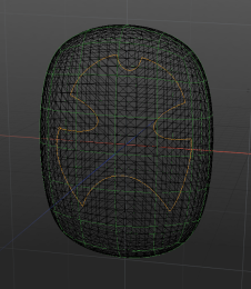
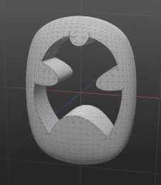
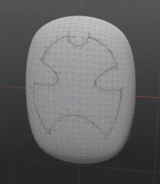
This example shows a curve applied to one of the Fusion Qbic Presets first as a Subtractive Trim, then as a Surface Strip.
|
|
|
|
|
Original |
Subtractive Trim |
Surface Strip |
Curve Input Properties
The Curve input settings help you adjust how your curve is converted to B-Spline and how geometry is extruded during MeshFusion. To access them:
| 1. | Select your curve in the Item List. |
This opens the Properties tab on the lower right panel.
| 2. | In the Mesh sub-tab, scroll down to the Mesh Fusion Curve Input section. |
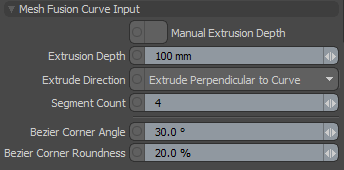
|
Manual Extrusion Depth |
When enabled, you can specify the Extrusion Depth value. When disabled, Modo uses the default. |
|
Extrusion Depth |
Specifies how far meshes are extruded from the curves when Manual Extrusion Depth is enabled. |
|
Extrude Direction |
Specifies the way meshes are extruded. The options are: • Extrude Perpendicular to Curve - The surface is extruded perpendicular to the plane of the curve, to a specified distance. This works well if the curve is flat, that is, it doesn't deviate from a plane. • Extrude Along Surface Normal - The curve is treated as a 3D curve and the surface produced from it is used as a trim. The cutting surface is extruded in the direction perpendicular to the surface being cut. This works for creating a surface strip on any curved surface by laying down the curve on that surface using the Mesh Constraints tools. |
|
Segment Count |
Specifies the number of B-Spline segments used when converting Bezier curves to B-Spline. Bezier curves can only be converted to B-spline approximately. The greater the number of B-Spline control points, the closer the approximation. Increasing the number of B-spline segments provides greater accuracy, but too many segments can reduce performance and increase output mesh density. For smooth Bezier curves without sharp angles, even a limited number of B-Spline segments is enough. |
|
Bezier Corner Angle |
The corners on a Bezier curve are automatically rounded when it's converted to a B-Spline. This specifies a threshold for rounding corners. Only the sharp corners where the change in direction is significant enough are rounded. Shallower corners are rounded by a very smooth curve, essentially becoming non-corners. |
|
Bezier Corner Roundness |
This value specifies the strength of the rounding effect. |
Sorry you didn't find this helpful
Why wasn't this helpful? (check all that apply)
Thanks for your feedback.
If you can't find what you're looking for or you have a workflow question, please try Foundry Support.
If you have any thoughts on how we can improve our learning content, please email the Documentation team using the button below.
Thanks for taking time to give us feedback.