Search is based on keyword.
Ex: "Procedures"
Do not search with natural language
Ex: "How do I write a new procedure?"
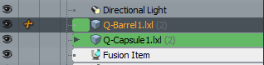
Fusion Item
A Fusion Item is added to the Item List each time a new Fusion model is created. It generates the final Fusion model and offers a range of properties for editing the result.
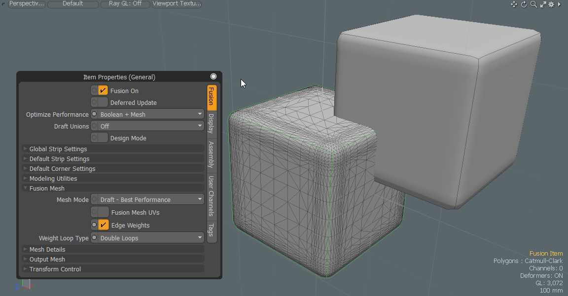
Fusion Item Properties
A Fusion Item includes the following properties:
|
Fusion Item |
|
|---|---|
|
Fusion On |
Enables/disables the evaluation and display of the Fusion Item |
|
Deferred Update |
When enabled, the mesh is only updated on mouse up. This is useful when you're editing complex meshes and continuous updates are not smooth. Note: Deferred updating doesn't work smoothly while Preview is open and active. Pausing Preview while editing in the 3D viewport allows deferred updating to perform normally. |
|
Allows you to optimize MeshFusion performance by caching Boolean operations, or caching meshes (strips and surface patches). Both forms of optimization limit the reevaluation of the Fusion Item to those elements affected by the current editing operation. Note: Mesh caching is only applied if the Mesh Mode is set to Draft The following options are available: • Off - optimization is disabled. • Boolean - caches Boolean operation only. • Boolean + Mesh - both Boolean and mesh caching is enabled. This is the default and recommended setting. Note: MeshFusion only takes advantage of mesh optimizations when the Fusion Item’s Mesh Mode is set to Draft. Best performance is achieved when optimization is used in conjunction with Deferred Update. |
|
| Draft Union |
Improves the performance while working on a model by automatically and adaptively splitting the Fusion Item into active and inactive parts. The active part contains all Primaries and Trims necessary for the current editing, based on the selected Source Mesh. No Fusion strip geometry is generated or displayed in the 3D viewport for the active part. Instead, normal z-buffering is used to increase rendering efficiency. For information on Primaries and Trims, see Mesh Roles and Relationships. The inactive part contains all of the Fusion objects remaining (not selected) from the Source Meshes. Fusion strip geometry is generated and displayed in the 3D viewport for the inactive parts. The following options are available: • Off - the entire Fusion model is reincorporated. All Unions are evaluated and all Fusion strips are restored and displayed in the 3D viewport. • Dynamic Separation - When activated, the model is split into two parts; the active part that you are editing and the other inactive parts you are not editing. The Fusion strip geometry at the junction of the union is not displayed for the active selected source mesh. All of the Fusion strip geometry at the junction of the unions are displayed for non-selected items (inactive parts). Note: There is a delay at the start of editing if the selection has changed (the length of delay is related to complexity of the Fusion Item). • Full Separation - When activated, the entire model is split into as many separate parts as possible to get the best possible performance. There is no selection-based reconfiguration and therefore no delay when editing begins. Fusion strip geometry at the junction of the unions are not displayed for active or inactive parts. |
|
Design Mode |
An internal override of various Fusion Item properties. When enabled, some Fusion Item and strip properties are internally overridden (but retained). Strips become extremely narrow and strip corners become sharp. The overridden properties are the following: • Strip Width • Strip Density • Corner Density • Corner Rounding Properties are restored when Design Mode is disabled. This mode is useful for improving performance, avoiding transient errors, and diagnosing meshing errors. |
|
Global Strip Settings |
|
|
Strip Rows |
The amount of rows of polygons that form the strip. |
| Strip Skirt Rows | Additional rows on the surface of the source mesh that provide better topology for post-MeshFusion modeling, such as corner rounding, or procedural modeling of a Fusion item. |
| Skirt Outer Rows | The amount of Strip Skirt Rows that run parallel to one another at a constant width along their entire length. |
|
Corner Smoothing |
The smoothing of Strip Corner quads. 0 is maximum sharpness. |
|
Use Absolute Strip Widths |
Set strip widths by absolute distance (in millimeters) or relative distance (in percentage). Toggled by Switch Width Mode. |
|
Switch Width Mode |
Toggles Use Absolute Strip Widths. |
|
Abs Strip Quad Length |
Sets strip quad length to an absolute distance. This is a global setting which only applies to all of the Fusion Item's strips. |
|
Default Strip Settings |
|
|
Strip Length Abs |
Sets the default strip quad length as the absolute distance. This may be overridden by individual Strip Item settings. |
|
Base Quad Length |
Sets the length of quads along a strip relative to adjacent quad sizes. |
|
Adaptive Quad Length |
This option increases strip density based on curvature. |
|
Strip Width Abs |
Sets the strip width as an absolute distance. Note: Editing the individual Strip Item settings overrides the defaults. |
|
Strip Width |
Strip width as a percentage of the original mesh quad size. Enforces the constant width regardless of edge angle. Note: Editing the individual Strip Item settings overrides the defaults. |
| Skirt Width |
Skirt width as a percentage of the original mesh quad size. Note: Editing the individual Strip Item settings overrides the defaults. |
| Skirt Width Abs |
Sets the skirt width as an absolute distance. Note: Editing the individual Strip Item settings overrides the defaults. |
| Skirt Outer Width |
Sets the skirt outer row width as an absolute distance. This is subtracted from the the Skirt Width Abs value, and should always be less. Note: Editing the individual Strip Item settings overrides the defaults. |
|
Strip Profile |
Determines the bevel amount. 0% is a flat bevel, 100% is fully rounded. |
|
Strip Smoothing |
Specifies the amount of corrective smoothing at sharp turns along the strip. |
|
Perpendicular Recovery |
Forces the strip crossing edges to quickly recover to perpendicular position. The distance of the recovery is specified in the Recovery Length property. Note: Some strip intersections require crossing edges to be non-perpandiular. • Off - Cross edges return to perpendicular gradually over the entire strip segment length. • Linear - Cross edges return to perpendicular linearly over specified Recovery Length. • Smooth - Cross edges return to perpendicular smoothly (ease in and out) over specified Recovery Length. • Ease Out - Cross edges return to perpendicular easing out over specified Recover Length. |
|
Sets the distance of the crossing edges to return to be perpendicular. |
|
|
Default Corner Settings |
|
|
Corner Density |
Strips density ration near corners. |
|
Corner Rounding |
Strips edge rounding near corners. |
| Modeling Utilities | |
|
Source Mesh Visibility |
Toggles the visibility of source meshes. |
|
Select Source Meshes |
Selects all source meshes. |
|
Select Entire Schematic |
Select all items. |
|
Set Output SubDs to Current |
Sets the preferred output subdivision levels of all source meshes of the Fusion Item to their current subdivision levels. |
|
Use Output SubD Levels |
Sets the subdivision levels of all source meshes of the Fusion Item to their preferred output subdivision levels. |
|
Use Working SubD Levels |
Sets the subdivision levels of all source meshes of the Fusion Item to one less than their preferred output subdivision levels. |
|
Converts pre-10.2 Fusion Items to the new workflow, updates Fusion Items edited in the Schematic to the new workflow. Note: Fusion models manually created or edited in a Schematic viewport are not compatible with the new workflow. However, it is possible to work with an entirely manual Schematic Fusion model. For more information, see Legacy Fusion Items. |
|
|
Delete Fusion Item |
Removes the Fusion Item, keeping the source meshes. |
|
Fusion Error Check |
Checks for known internal errors. |
| Fusion Mesh | |
| Mesh Mode |
Specifies the mesh type for the 3D viewport display and output. The following options are available: • Draft - Best Performance - Recommended for full performance optimization. This option is not recommended for Output (Strips and Surfaces are not unified). • Airtight Draft - Sets to the minimum airtight properties. Strips and surfaces are unified but no further refinement or optimization of the mesh is performed. This option may be slightly faster than other airtight mesh modes. • Airtight Final - Uses properties to produce the best topology output. Strips and surfaces are unified. Closely spaced vertices are merged. Pairs of tri-polygons are converted to quads where possible. No Selection Sets, Parts, or Material groups are created. • Airtight Final w/Parts - Uses the same mesh topology properties as Airtight Final and creates polygon Selection Sets, Parts, and Material groups. These are helpful when making selections for material assignment or further modeling of the output mesh. When set, it creates individual materials for each seam-enclosed part. Each part is an individual patch. A patch is a group of polygons surrounded by a loop of seams or strips. • Airtight Final Item Parts - Creates the same mesh topology as the Airtight Final mode. Like Airtight Final w/Parts, this option creates polygon Selection Sets, Parts, and Material Groups. However, those polygon sets are based on the source meshes rather than individual patches (groups of polygons surrounded by a loop of strips). Complex models containing many intersecting surfaces may generate dozens or hundreds of parts when using Airtight Final w/Parts. With this option, one Part/Material/Selection Set per source mesh is created. |
|
Strip Polys Only |
Creates only the strip polygons. The surface mesh is not generated. This is useful for procedural and direct modeling based on strips. For example, feeding this fusion item into a procedural using a Merge Meshes operation. This makes it easier to select this geometry to modify.
|
| Fusion Mesh UVs |
Creates Mesh UVs for display and output. Note: The source mesh must have UVs. For more information, see Create UV Tool. |
| Edge Weights | Creates simulated CC edge weighting by internally adding loops to the source meshes. |
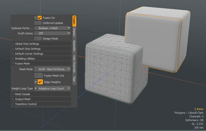
| Weight Loop Type |
MeshFusion simulates Catmull-Clark edge-weighting by internally adding edge loops to the source meshes (original source meshes are unchanged). The following options are available: Double Loops - Adds two edge loops on either side of each weighted edge. Provides best fidelity to the CC surface, but produces denser Fusion meshes that may slow performance.
Single Loops - Adds a one edge loop on either side of each weighted edge. This option produces a surface that is often indistinguishable from that created with Double Loops. It produces cleaner, less dense, Fusion mesh items. Note: With certain source mesh topologies, fidelity to actual CC surface may be lower and greater Fusion SubDiv levels may be automatically enforced (effectively canceling the lower density benefits).
Adaptive Loop Count - Determines the best loop count (single or double loops) based on the nature of source mesh topology. Double loops are only created on those edges where single looping have fidelity and density requirement disadvantages.
|
| Mesh Details | |
| Relax Mesh Topo |
Relaxes the mesh topology to produce more uniform polygons. Note: This option is usually not needed or recommended. It slows performance (especially with high iteration values), and may cause surface irregularities as described below. You should only use this option if you have problems with further modeling of the output mesh. Note: Applies to Final Mesh Mode types only. |
| Relax Iterations |
Determines how much the mesh relaxes and how far away from the strips the relaxation spreads. Specify the number of mesh topology relaxation iterations. The default value is 32. Note: Applies to Final Mesh Mode types only. |
| Relax Range |
Determines how much the mesh relax range is. The Relax Range is measured in quads from the strip edges. The default value is 4. Note: Applies to Final Mesh Mode types only. |
| Remove Close Verts |
Merges very closely spaced vertices along strip boundaries. Generally, this is helpful to produce lighter and cleaner meshes. However, when outputting very low density meshes surface irregularities can be introduced, creating denting and lumpiness around strip corners. The percentage value determines how aggressive Fusion merges the vertices. Lower values raise tolerances based on distance and curvature. |
| Cage Vertices |
Uses cage vertices of the source meshes. This is useful for creating very low density Fusion meshes from simple, angular source meshes. Normally, source meshes are interpreted as Catmull-Clark surfaces, which means their vertices move significantly from there original ‘cage’ locations. When creating Fusion meshes based on simple, angular meshes and low Fusion SubDiv levels (0 or 1), this option maintains that angular quality by not allowing that CC shift. The vertices of the Fusion mesh remain identical to the source mesh. Note: This is not recommended for curved surfaces. |
| Extra Strip Row |
Adds an extra row of edges along strip boundaries lying on the adjacent surface. This effectively ‘insulates’ the irregular polygons found at the surface/strip boundary, allowing those parts of the mesh to be edited (for example, moved relative to each other) without the surface anomalies that typically occur when disturbing those irregular polygons. This is useful for some specific post-Fusion modeling methods. Note: This is ignored when the Mesh Mode type is set to Draft. |
| Output Mesh | |
| Dup & Convert to Mesh |
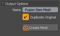
Creates a frozen copy of the Fusion mesh. Options vary based on the Mesh Mode used. If the Mesh Mode is set to Airtight Final, the following dialog displays:
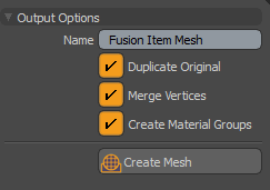
If the Mesh ModeMesh Modes set to Airtight Final w/Parts or Airtight Final Item Part, the following dialog displays:
Tip: Alt + Click skips the display of the Output Options dialog and converts the mesh immediately, applying the last-used settings set. The following options are available: • Name - Allows you to provide a unique name for your output. • Duplicate Original - Converts the original Fusion Item. Recommended: Your original Fusion Item may be more reliable than a copy. We recommend to always enable this option. • Merge Vertices - Ensures that you get a single unified mesh; an airtight mesh. Note: We recommend to enable this option. The only exception is when you want to have a disconnected mesh. For example, where the surface and strip portions are not contiguous. • Create Materials Groups - Creates a container to hold material polygon groups. To view a list of materials created, open the Mesh Ops Lists tab and Statistics sub-tab and then expand Polygons > Material. Individual materials are listed for each source mesh used in your Fusion Item, using the source mesh name from which they came from. The Materials are also available in the Shader Tree. From the Shader tree you can select a material group and modify their properties. For more information, see Material Group. Note: You won’t be able to use materials that require UV’s unless the Fusion Mesh UVs option is enabled and the source meshes contain UVs. • Create Mesh - Allows you to provide a unique name for the new Mesh Item. Tip: When you have enabled either the Airtight Final w/Parts or Airtight Final Item Parts Mesh Mode, you can view a list of your parts by opening the Lists tab and expand Polygons > Part. Select the <Fusion Item> Strips item to view all of the polygons that belong to all of the strips used in your model. This is handy for advanced users who use scripting to manage their models. |
| Duplicate Fusion Item | Creates a duplicate Fusion Item. |
| Convert to Mesh Item | Creates a Mesh Item from current Fusion Item. |
| Transform Controls | |
| Position | Uses the X, Y, and Z input fields to apply specific offset distance values (calculated from the position the object was in when the tool was activated). When adjusting an object interactively in the viewport, the Position input fields display the current offset distance applied, providing useful user feedback. |
| Rotate | Uses the X, Y, and Z input fields to apply specific rotation values. When adjusting an object interactively in the viewport, the Rotation input fields display the current offset distance applied, providing useful user feedback. |
| Scale | Uses the X, Y, and Z input fields to apply specific scaling values. When adjusting an object interactively in the viewport, the Scale input fields display the current scale factor applied, providing useful user feedback. |
| Reset | Resets the selected transform values to (0,0,0) returning the items to their default state. |
| Zero | Resets the chosen transform property values to 0, leaving the center position and item position intact. |
| Add | Adds transform items. Transform items are the channel groups associated with an item that store its transform values, controlling its position, rotation and scale. By default, new items do not have any transform items associated with them, even though they are visible within the Properties panel. This is useful as an optimization as only the necessary transforms are added on an as-needed basis, reducing scene overhead. There are several ways to add them. You can simply transform the target item with one of the various transform tools, or by editing the value input fields. This action causes the particular transform item to be added automatically to the Channels viewport list. The Add function here can also be used to add the selected set of transforms to the channel list while keeping the default 0,0,0 values. A necessary step for referencing, in order to override the channels, they must first exist. |
| Realign Source Meshes | Re-aligns your source meshes to your Fusion Item. When enabled the source meshes are moved back into the place relative to the moved Fusion Item. The Position X, Y, and Z are transformed to zero and the Fusion Item is no longer offset from the source meshes. |


Related Videos
Draft Union
Material Grouping
Transforming Fusion Items
You can use the traditional Modo transform tools to move, rotate, and scale your Fusion Item and its source meshes. For more information on the transform tools, see Transforming Items.
By default, the Fusion Item always exists where its source meshes are located. However, you can transform your Fusion Item separately, detaching it from its source meshes.
To do this:
| 1. | Select the Fusion Item in the Item List. |
| 2. | Activate the relevant transform tool and use the tool handles to move, rotate, or scale the item. |
Alternatively, in the Fusion Item's Properties tab, go to Transform Control, and edit the appropriate fields.
Note: The transform values indicated under Transform Control are not the Fusion Item's position, rotation, or scale values in world space, but the values relative to its source meshes.
You can re-align your source meshes to your Fusion Item by clicking the Realign Source Meshes button under Transform Control.
Click the image below to view an animation.
![]()
Legacy Fusion Items
Fusion models manually created or edited in a Schematic viewport are not compatible with the new workflow. However, it is possible to work with an entirely manual Schematic Fusion model. At any time you can convert a manually edited schematic to work with the new workflow using the Convert Fusion Schematic function. Once done, they can be modified with the latest Fusion tools.
The same is true for models you manually edit in the Schematic Fusion layout. Schematic Fusion is not compatible with the new workflow, so after manually adjusting your model, you need to update it.
To convert a Fusion Item to the new workflow, follow these steps:
| 1. | In the Item List, select the Fusion Item. |
The item's properties display in the Properties panel in the lower-right.
| 2. | Under Modeling Utilities, click the Convert Fusion Schematic button. |
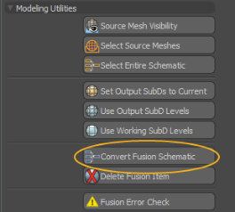
Your Fusion Item is converted to the new workflow and you can start editing it.
Sorry you didn't find this helpful
Why wasn't this helpful? (check all that apply)
Thanks for your feedback.
If you can't find what you're looking for or you have a workflow question, please try Foundry Support.
If you have any thoughts on how we can improve our learning content, please email the Documentation team using the button below.
Thanks for taking time to give us feedback.