Search is based on keyword.
Ex: "Procedures"
Do not search with natural language
Ex: "How do I write a new procedure?"
Create UV Tool
The Create UV tool provides several methods and options for generating the UV maps. If you have not selected any polygons, the tool uses all visible foreground polygons to create the UV map. To isolate certain areas of your model, select the polygons before using the tool. The Create UV tool works by projecting the polygons from 3D space into the 2D (UV) space. As such, it is important to specify the most appropriate projection type. Using the Create UV tool to create a UV map is often only part of the process because this tool generally results in UV maps that need some manual editing to complete.
Modo stores UV maps as discontinuous 2D Vertex Maps for 0 -1 UV coordinate data. You use UV maps to explicitly link vertices in the 3D mesh to locations on a 2D image for accurate texture mapping. The UV map can be considered as a method to lay out a 3D mesh so that it lays flat for the 2D image to be applied to the mesh accurately. Modo provides a UV view to help you visualize the UVs over a bitmap image. You can use the UV layout to see mesh geometry in the viewport and the UV map.
Tip: Use the Distortion Compensation option when you create a primitive that does not have equal radius values. For more information, see Managing Distortions.
The Create UV tool is available in a number of places in the interface:
• UV layout: In the Toolbox on the left panel, open the UV tab and click Project. The Create UV properties are listed in the bottom of the Toolbox panel.
• Model layout: In the Toolbox on the left panel, open the UV tab and click Project. The Create UV properties are listed in the bottom of the Toolbox panel.
• Procedural Mesh Operation: Open the Mesh Operations tab on the right panel, click Add Operator, expand the UV category, and click Create UV Map. The properties are displayed in the right panel.
Creating UVs using the Direct Modeling Toolbox tool
The following is an example of creating a UV map using the Teapot primitive.
To generate UVs with the Toolbox Create UV tool:
| 1. | Open the UV layout. |
| 2. | In the menu bar, click Geometry > Primitives Tools > Teapot. |
This is an example. You can work with other meshes.
| 3. | In the Toolbox on the left pane, set the teapot Size to 1m and then click Apply. |
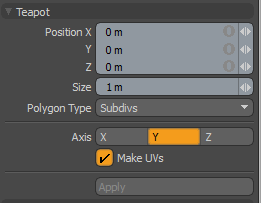
| 4. | In the Toolbox on the left pane, click Project. |
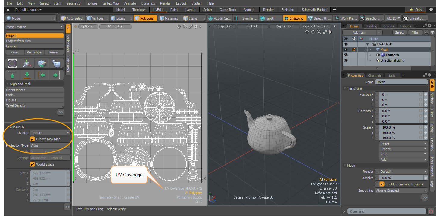
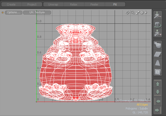
Modo generates a UV map, which appears in the UV Texture view. In the Toolbox in the left pane, the Create UV options are displayed.
Alternatively, you can specify another UV Map previously created by selecting it from the UV Map dropdown menu. If you want to create a new UV map, click Create New Map.
| 5. | Set the Projection Type is set to Atlas. |
Creating UVs in the Schematic Viewport
The following is an example, using the Hippopotamus preset and creating a UV map.
| 1. | Directly below the menu bar, in the switcher bar, click Layout > Model. |
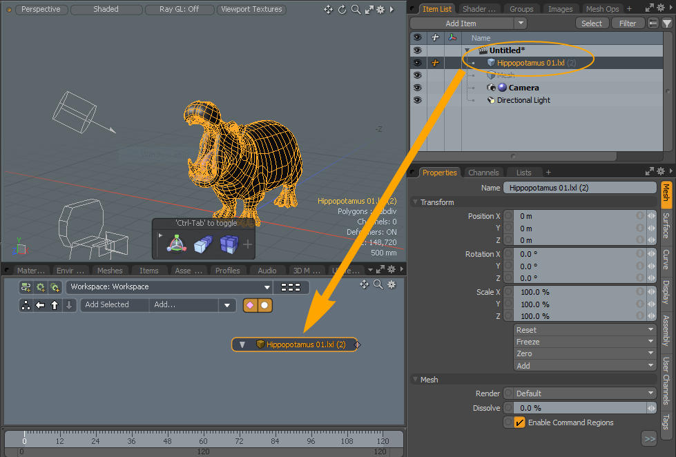
| 2. | Press Fn + F6 on your keyboard to open the Presets, expand Assets > Meshes > Animals, and double-click Hippopotamus 01. |
For more information, see Preset Browser.
| 3. | Close the Preset Browser dialog. |
| 4. | In the right pane, open the Items List tab and drag the Hippopotamus 01 item into the Schematic viewport. |
Tip: If the Schematic tab is not displayed in the viewport, click the plus button and select Utilities > Schematic.
The Hippopotamus displays in the 3D viewport and the Schematic viewport.
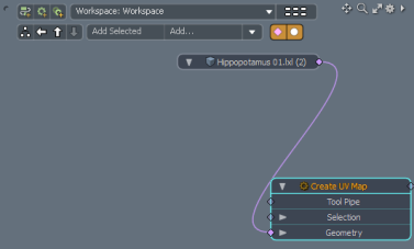
| 5. | In the Schematic viewport, click Add, expand Mesh Operations > UV, and double-click Create UV Map. |
The Hippopotamus 01 item links to the Create UV Map item.
| 6. | In the Schematic viewport on the bottom of the view, click the New Tab button on the top right corner of the tabs listed. |

| 7. | Select New Tab > Data Lists > Vertex Map List. |
| 8. | In the Vertex Map List viewport, click UV Maps and double-click Texture. |
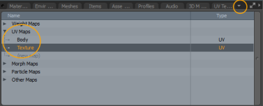
The UV Editor displays the Hippopotamus in the UV space.
| 9. | In the right pane, open the Items List tab, click the plus button beside the Hippopotamus item and then click Create UV Map. |
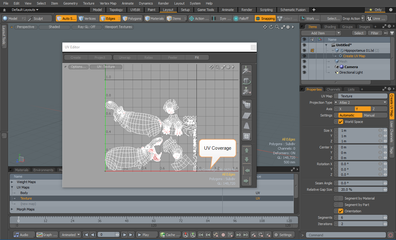
| 10. | In the Properties pane, change the Projection Type to Atlas2. |
The Hippopotamus 01 mesh displays and updates in the UV Editor.
Tip: The UV Coverage value is displayed at the bottom right corner of the UV Editor, which shows the amount of uniform UV space of the total region that is covered by geometry. This option is useful to game workflows, when trying to maximize the amount of texture space being used for the target surface. When you use an UV editing tools, the coverage is updated at the end of the editing process.
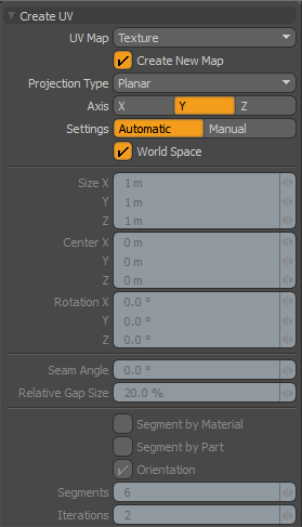
Create UV Options
The following options are available:
|
Option |
Description |
| Allows you to select a UV texture map to project UVs. You can explicitly choose the destination texture map from the dropdown menu. | |
| Create New Map | Creates new texture map if the mesh does not have a UV map using the specific name selected in the UV Map option, otherwise it does not create a new map. |
|
Projection Type |
Specifies the type of projection used when creating the UV map. Planar - Projects the selected polygons from an orthogonal view determined by the Axis setting. The resulting UV map actually looks quite similar to viewing the model in a 3D viewport set to Top, Front, or Side. Use this mode for quickly assigning areas of a mesh that are all facing the same direction. For more complicated geometry (such as a head), Planar results in a significant amount of UV overlap (such as the projection places polygons on both sides of the head into the same UV coordinates). A Planar projection is good for landscapes and some architectural or hard-surface models. Cylindrical - Projects the polygons into the UV map based on a virtual cylinder that surrounds the mesh. If you consider the cylinder as a soda can and set the Axis to Y, the can sits on a table, but if you set the Axis to X or Z, it lies on its side. Use Cylinder for mapping specific areas of a model (such as arms) with organic meshes or for tubes and pipe segments with hard-surface meshes.
Spherical - Projects the UVs from a virtual sphere that surrounds the mesh. Modo places the poles of the sphere based on the Axis setting. The Y axis setting places the poles up and down; an X axis puts them side to side; and a Z axis puts them front to back.
Atlas - Uses a multi-faceted projection method to place all polygons into the UV map and maintains the relative scale based on the 3D volume of the polygons. This is designed to minimize any texture distortion from non-uniform UV data. However, the Atlas projection results in a highly discontinuous UV map, which may be useful only for certain algorithmic uses, such as texture baking.
Barycentric - Forces each individual polygon to fill the 0 to 1 UV space. Quadrangular polygons fit perfectly to the outer bounds of the UV area. Modo places triangles and other polygons within the UV space as best as it can. If you have a texture that you want to tile across every polygon in the mesh, this can be a very useful mode.
Atlas 2- Attempts to fill the UV space with all selected polygons in the most efficient way without distorting the relative scale of each polygon from 3D to 2D space. This is similar to Atlas mode. Cubic - Projects the UVs from the polygons depending on their normal direction and segmented by the six planar directions: Top, Bottom, Left, Right, Front, and Back. This mode is similar to a Planar projection, however, it avoids the common backward texture errors that can result from Planar projections. |
|
Axis |
Sets the main axis direction for generating the UV projection. |
|
Settings |
Specifies how Modo scales the UV projection.
Automatic - Sets the scale of the UV projection in a manner to best fill the total available UV space based on the selected mesh's bounding box. Manual - Uses the Size, Center, and Rotation settings to define a specific projection that affects the overall size of the final UV map. |
|
Seam Angle |
Specifies at what angle a seam appears in the UV map for Cylindrical and Spherical projections that have a seam. For example, if your model has a face and it happens to be turned in a way that creates a seam across the face, you can adjust the seam angle to place it in the back of the head without changing the geometry. |
|
Relative Gap Size |
Produces a greater distance between individual UV islands when using one of the atlas projection types that generate multiple pieces (or islands). |
|
Segment By Material |
When enabled, creates additional island segments with atlas projection types so that individual islands never have polygons from more than one material tag. |
|
Segment By Part |
When enabled, creates additional island segments with atlas projection types so that individual islands never have polygons from more than one part tag. |
|
Orientation |
When enabled, forces UV islands to flip based on their axial direction when used with atlas projection types. For example, if you select this option with a head, Modo maps one side of the head to mirror the other side. This makes it easier to distinguish one side from the other. For Atlas 2 projections, this checkbox is always selected. |
|
Segments |
Determines (roughly) the number of generated UV islands when using the Atlas 2 projection type. |
|
Iterations |
Generates UV islands, with the Atlas 2 projection type, by grouping together polygons with similar normals to reduce overall distortion. Increasing the Iterations value, increases Modo's sensitivity to the normal direction. This generates less distortion with more UV islands. |
Sorry you didn't find this helpful
Why wasn't this helpful? (check all that apply)
Thanks for your feedback.
If you can't find what you're looking for or you have a workflow question, please try Foundry Support.
If you have any thoughts on how we can improve our learning content, please email the Documentation team using the button below.
Thanks for taking time to give us feedback.