Search is based on keyword.
Ex: "Procedures"
Do not search with natural language
Ex: "How do I write a new procedure?"
Bezier
The Bezier tool allows you to create a curve defined by control vertices. This tool works like the Pen tool. Bezier curves are a subset of Non-uniform Rational B-spline (NURBS) curves that are composed of two types of control vertices, anchors and tangents. Anchors lie on the curve and determine the origin of the tangents. The tangents determine the shape of the curve leading to an adjacent anchor. Depending on the Mode option, slightly different components draw in the interface.
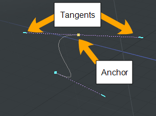
Each time you click in the viewport with the Bezier Curve tool activated, you create an anchor which has no tangents and a sharp corner is created on your curve. When you continue to click in the viewport, additional points are added to the curve.
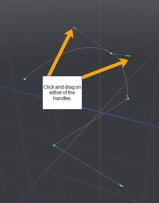
When you click and drag in the viewport, an anchor and a pair of tangents are created. Dragging moves the tangents to shape the curve. By default, both sides of the tangent move together.
The following animation illustrates the workflow.
Activating the Bezier Curve Tool
To activate the direct modeling Bezier tool:
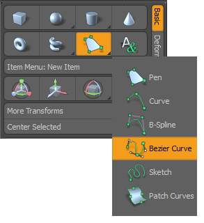
• In the Basic sub-tab of the modeling toolbox, right-click the Pen ![]() tool to reveal additional options, and click Bezier Curve.
tool to reveal additional options, and click Bezier Curve.
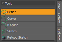
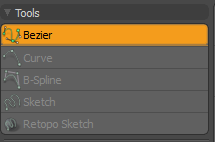
• Alternatively, in the Curve sub-tab of the modeling toolbox, under Tools, click Bezier.
Adding a Bezier Curve
| 1. | Click the Model layout on the switcher bar at the top of the UI. |
| 2. | In the Toolbox, open the Basic sub-tab. |
| 3. | Right-click the Pen |
| 4. | Click and drag in the viewport to define the first anchor for your curve. |
This splits the corner anchor into two points, that move out along the segments, to create a rounded curve section between the straight segments.
| 5. | Click and hold in another position and drag out the tangent handles to shape the curve. Repeat to add additional points on your curve. |
Click on the image below to view an animation.
To change the tangent angle at an anchor, enable Polygons selection mode, click on a tangent handle, and drag it into a new position. The sharpness of the corner changes. To reposition an anchor, enable Polygons selection mode, click on an anchor, and drag it into a new position.
Editing a Bezier Curve
While drawing, you can hover over any point or handle where it turns yellow. You can then click-and-drag the anchor or handle to further edit the curve.
To move only one side of a tangent, click on the tangent handle and drag it into another position.
Once you drop the tool by pressing the Space key, interactive editing is lost but you can re-activate the editing ability by selecting the curve in Polygons selection mode.
Deleting Control Points
To remove an anchor:
| 1. | In the right panel, click Tool Properties. |
This opens the Tool Properties panel.
| 2. | Set Mode to Delete. |
| 3. | Click any of the control points to delete them. |
Changing a Bezier Curve to Different Curve Type
You can change Bezier curves to B-Spline curves or standard curves depending on what you want to achieve in your scene. The Curve Convert mesh operation allows you to convert your selected curves to another specified curve type.
For more information, see Curve Convert.
Example
To change the curve type:
| 1. | In the Model layout, open the Curve tab on the left panel, and click Bezier. |
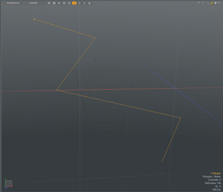
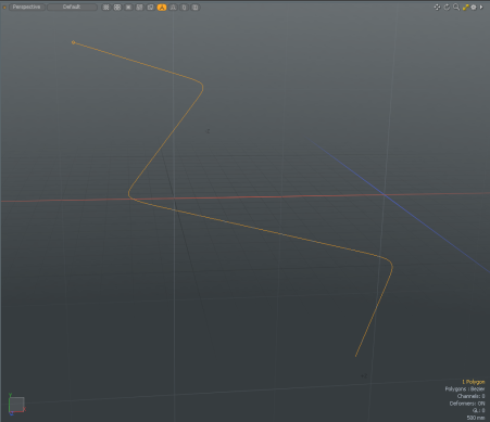
| 2. | In the 3D viewport, click in several locations to create a Bezier curve, and press the Space key to drop the tool. |
| 3. | Open the Mesh Ops tab on the right panel and click Add Operator > Curves > Curve Convert. |
Tip: If the Mesh Ops tab is not visible on the right panel, click the More Tabs or New Tab icon and select New Tab > Data Lists > Mesh Ops.

| 4. | Select the source and target curve type you wish to transform. In this example, on the Properties tab, set From to Bezier and To to B-Spline. |
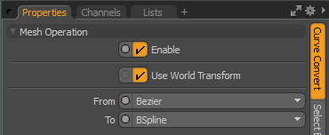
The Bezier curve is converted to a B-spline curve.
Editing a Bezier Curve
Once you drop the tool, interactive editing is lost but you can re-activate it by selecting the curve in Polygons selection mode.
For more information, see Polygon Selection Mode
Bezier Curve Properties
 f
f
|
Mode |
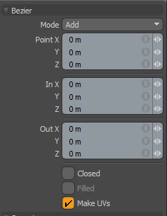
Specifies the Bezier Curve mode. The following options are available: • Add - Adds anchors along a curve. This is the default mode. • Edit - Freely click-and-drag any of the anchors along the curve to change the look to the desired shape. • Delete - Click any of the anchors along the curve to remove it. |
|
Point X, Y, Z |
Allows finer point control by assigning specific X, Y, and Z values in these input fields for the currently-selected anchor. |
|
In X, Y, Z |
Allows finer handle control by assigning specific X, Y, and Z values in these In input fields for the currently selected (highlighted) anchor. |
|
Out X, Y, Z |
Allows finer handle control by assigning specific X, Y, and Z values in these Out input fields for the currently selected (highlighted) anchor. |
|
Closed |
Adds an automatic curve segment between the first and last anchor positions, producing a closed curve. Tip: Alternatively, to create a closed curve, right-click on the first anchor in the viewport. |
|
Filled |
When the Closed option is enabled, you can additionally enable the Filled option to create a renderable flat surface that is defined by the outlining curve itself. The resulting surface can be tagged like a polygon for adding material definitions. |
|
Make UVs |
Activates auto-generation of UV texture coordinates along the curve. The generated UV values are of a single vertical line (V axis in UV), positioning all the anchor vertices evenly between 0 and 1. For example, this can be useful for applying a gradient to a rendered curve (the Render Curves option is available in the Mesh Item properties. |
Sorry you didn't find this helpful
Why wasn't this helpful? (check all that apply)
Thanks for your feedback.
If you can't find what you're looking for or you have a workflow question, please try Foundry Support.
If you have any thoughts on how we can improve our learning content, please email the Documentation team using the button below.
Thanks for taking time to give us feedback.