Search is based on keyword.
Ex: "Procedures"
Do not search with natural language
Ex: "How do I write a new procedure?"
Topology Pen
When creating high-resolution assets with functions such as multi-resolution sculpting, you may create geometry that would be difficult to rig and animate. You could have geometry with too many vertices or with little attention paid to surface topology. These and similar things can lead to odd, unrealistic deformations. The solution for getting a free-form, high-resolution model into a format where it can be easily animated is to retopologize the model. To re-structure geometry, you take a high-resolution mesh and use that as a base to generate a much lower resolution mesh. The lower resolution mesh can have more thoughtfully placed geometry that is easier to weight and rig. From there, you can bake a displacement map to create in a final asset that is visually the same as the free-form geometry, but a lot lighter to provide better deformations and smoother interactivity when animating.
To facilitate retopologizing models, you use the Topology Pen tool to create that lower-resolution mesh. This combined with the Pen tool and Sketch tool set to a Background Point Constraint should be all that you need to completely retopologize any high-resolution geometry.
The Topology Pen tool is found in the Model layout Toolbox, under the Polygon sub-tab. It is also found in the Topology layout Tools sub-tab. The Topology layout is dedicated to the functions of retopologizing models and provides all the related tools and settings in a single convenient viewport.
Note: Previously the Topology Pen tool was known as the Drag Weld tool. When features were added to increase its usability, it was renamed, but the functionality remains.
Using the Tool
Retopology works with a high resolution mesh as a background element. (It is visible in the Item List, but it is unselected.) Next, make sure Modo is in Polygons component mode (not Items mode). Create a new empty mesh layer by pressing N. Select the new mesh layer in the Item List. (Rename it if you wish.) Place some initial geometry with either the Pen Tool (possibly using Quads mode to lay down strips of quadrangle polygons) or the Topology Sketch Tool (which also lays down a series of quadrangle polygons along a drawn curve that conforms to the background surface). Once you map out the basic contours, you can activate the Topology Pen tool and begin to extend edges and adjust the geometry into the final surface. The Topology Pen tool, depending on settings, offers a broad range of functions. Some functions even duplicate those of other tools to provide a more convenient and fluid workflow. It also enables you to smooth and even out the spacing between vertices on a surface to clean up topology.
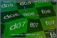
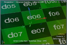
By default, the Topology Pen tool also activates a Background Constraint type of Point to ensure that all created vertices lie directly on the surface of the background mesh. To use, click the Topology Pen icon in the Topo interface tab's toolbox. In its Properties panel select the proper mode and options, and then manipulate the geometry in the 3D viewport. You can see the geometric element to edit by the pre-highlighting (drawing a ghosted color over the element as the you move the pointer). Dragging applies the defined action, represented by a small yellow box. When you move the box, Modo displays the distance as the Offset X/Y/Z values.
Modo provides some shortcuts to use when the tool is in Move mode.
• Click = Move
• Right-click = Move Edge Loop
• Middle-click = Split
• Shift+click = Duplicate
• Shift+right-click = Duplicate Loop
• Shift+middle-click = Add Loop
• Ctrl+click = Slide
• Ctrl+middle-click = Remove
• Shift+ Ctrl + left click = Smoothing
• Shift+ Ctrl + right click = Smoothing + Edge Loop
Smoothing
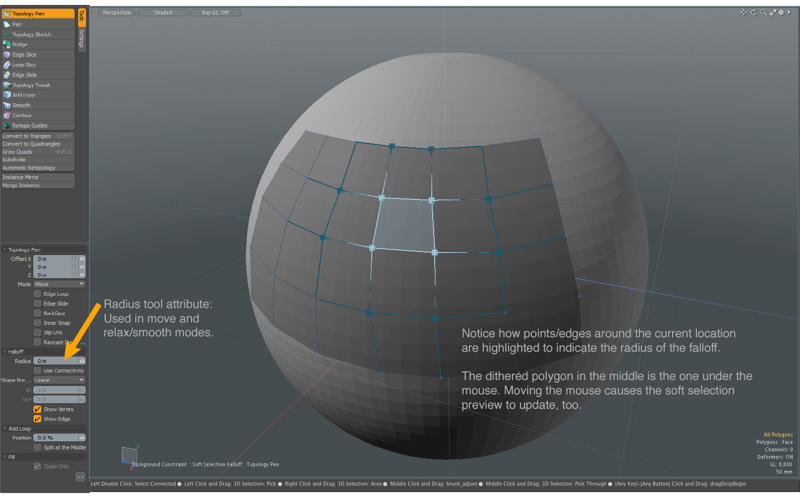
The Topology Pen tool has a smoothing feature which allows you even out the spacing between vertices on a surface to clean up topology. You can focus the smooth operation on a section of your mesh. As you drag, the point/edges around the current location are highlighted to indicate the radius of the falloff and the selected polygons relax into an even distribution.
Smart Snapping
The Topology Pen tool has a custom smart-snapping feature that automatically snaps edges together to weld them into a single vertex. Modo determines the snapping based on the proximity of vertices to each other as you drag an element. Modo indicates snapped edges by a purple color. The welding is not permanent until you release the mouse button; therefore, you can continue to drag and adjust the position of the element (and modifying the snapping) should the wrong vertex snap. You can snap individual vertices together by dragging one vertex onto another.
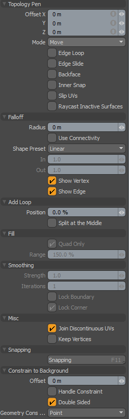
Topology Pen Properties
|
Topology Pen |
|||||
|---|---|---|---|---|---|
|
Offset X/Y/Z |
Specifies the distance the point of reference (a small yellow box) travels as you drag it in the 3D viewport. Once you set the location by clicking the mouse, you may also manually adjust these values directly to adjust the target component. |
||||
|
Mode |
Provides several modes that directly relate to the process of retopologizing geometry. • Move - Moves an element as you drag it, but it remains fixed against the background surface as it slides around. This is useful in editing vertices, edges, and polygons.
• Duplicate - Duplicates an edge as you drag it. With Edge Loop enabled or by dragging with the right mouse button, you can duplicate an entire edge loop simultaneously. This mode also duplicates individual vertices to make triangle polygons.
• Remove - Removes the element completely from the geometry. This mode does not modify individual outer edges, but removes interior edges, vertices, and entire polygons. Using the right mouse button removes an entire loop.
• Split - Creates an edge, which can then be dragged over and snapped to an adjoining vertex, when dragging a vertex. This splits the geometry with a new edge.
• Add Loop - Create a new edge across the entire span or loop of geometry until another edge or a triangle is encountered. Dragging interactively adjusts the position of the loop — unless you have Split at the Middle enabled.
• Point - Draws a one point polygon when you click the mouse and the pointer is in an empty area. If you click any geometry component in this mode, then the tool works as in the Move mode.
• Fill - Looks for nearby edges and points (vertices) and tries to automatically generate a quad or triangle polygon from them. You can use this mode to fill large areas with a grid of polygons after using the Point mode used to place the vertices. After placing vertices, switch to Fill mode and click in the center of where each quad (or triangle) polygon should appear to create the geometry. Modo pre-highlights the polygon to indicate what geometry it creates when you click. • Smoothing - Relaxes vertices by clicking and dragging elements in a falloff range. You can use this mode to clean up the topology of a mesh to even out the spacing between vertices on a surface, while constraining to the background. When Edge Loop is enabled, the vertices on the edge loop are relaxed along the curve. If the Radius of the Falloff is zero, all vertex positions are relaxed. Strength controls the amount of smoothing applied to the model. Iterations determines the number of times that Modo applies the smoothing. A combination of both Strength and Iterations controls the overall smoothing of the model. |
||||
|
When enabled, modifies an entire continuous loop of geometry until an opposing edge or triangle is encountered (instead of a single geometric element) when making any adjustments. |
|||||
|
Edge Slide |
When enabled, restricts the moving of edges and vertices to the positions of adjoining edges. This slides edges and vertices along the edges of neighboring geometry. Pressing Ctrl while in Move mode provides the same functionality. |
||||
|
Backface |
When enabled, snaps geometric components against the back side of a surface. Normally, when disabled, Modo ignores backward-facing polygons for snapping. |
||||
|
Innersnap |
When enabled, snaps any vertex to any other vertex regardless of its location (in the same layer). Normally, when disabled, Modo does not snap interior vertices for a surface (those with no open edges) to other interior faces because snapping only occurs between perimeter vertices. |
||||
|
Slip UVs |
When enabled, edits applied to the geometry do not change the existing UV map. UV values are generally fixed to specific vertices; therefore, further edits to the geometry may warp, deform, or otherwise distort the UV values in undesirable ways. When this happens, you may need to adjust the map or to redo it altogether. To avoid this undesirable result, you enable Slip UVs so as to not disturb any existing UV mapping applied to the geometry.
|
||||
|
Raycast Inactive Surfaces |
When enabled, hides certain foreground geometry components behind the background geometry where you cannot select them. This is useful when retopologizing layered elements. For example, when working from a side view with a character that has fingers, several fingers could overlap in the viewport to make it difficult for the Topology Pen tool to discern which edge to indicate for duplicating. With this option enabled, Modo ignores the foreground retopology geometry that is behind the nearest surface and occluded by the background object (the other fingers). In this case, only the retopology surface that is the closest to the viewer is active. This does slow the tool's interactivity, which is why this option is disabled by default. |
||||
| Falloff - The Falloff distance is very similar to the Selection Falloff tool. | |||||
|
Determines the range outside of the selected edge to attenuate the falloff.
|
|||||
|
Use Connectivity |
When enabled, only affects single surface/connected elements. Unconnected elements within the range are ignored. |
||||
|
Shape Preset |
The strength of the falloff's influence can be controlled along the extent using a shape preset. The following options are available: • Linear - Attenuation of the falloff occurs evenly across its range. • Ease-In - Strength of the falloff is greater toward the start position. • Ease-Out - Strength of falloff is greater toward the end position. • Smooth - Strength of falloff is greater toward the center of the falloff. • Custom - Use the In/Out options to fine-tune the strength of the falloff. |
||||
|
In |
When Custom is set for Shape Preset, use this option to set the incoming value to fine-tune the strength of the falloff. The In value determines the strength of the falloff nearer to the start position. |
||||
|
Out |
When Custom is set for Shape Preset, use this option to set the outgoing value to fine-tune the strength of the falloff. The Out value determines its strength nearer the end of the falloff. |
||||
|
Show Vertex |
Used to display the angular points of the polygons on a model. This option is enabled by default. |
||||
|
Show Edge |
Used to display the edges of the polygons on a model. This option is enabled by default. |
||||
|
Add Loop |
|||||
|
Position |
When enabled, determines the position along an edge where Modo adds the new line of polygon edges. Modo computes the position as a percentage along each edge encountered. After adding the loop by clicking in the 3D viewport, you can directly modify this value by adjusting the resulting position. |
||||
|
Split at the Middle |
When enabled, creates new edge loops fixed at the 50% (center) position. |
||||
|
Fill - The Fill options are only available when the Topology Pen tool is in the Fill mode. |
|||||
|
Quad Only |
When enabled, tries to force only four-sided (quad) polygons. |
||||
|
Range |
Determines the search area around the pointer when looking for vertices to convert to polygons. |
||||
|
Smoothing |
|||||
|
Controls the amount of smoothing applied to the mesh. |
|||||
|
Determines the number of times that Modo applies the smoothing. |
|||||
|
Lock Boundary |
When enabled, vertex positions on boundary edges are locked at the original positions. This option is disabled by default. Click the image below to view an animation.
|
||||
|
Lock Corner |
When enabled, vertices that are shared with one surface polygon on boundary edges are locked. This option is enabled by default. Click the image below to view an animation.
|
||||
|
Misc |
|||||
|
Copy Discontinuous UVs |
Specifies how to set discontinuous UVs after welding a 3D vertex pair. When enabled, the discontinuous UV from the source vertex of polygon is used for the new destination vertex, otherwise the UV of the destination vertex is used for the source vertex. This option is enabled by default.
|
||||
|
Keep Vertices |
When disabled, the end vertices of the edges are removed by the Remove mode operation with the Edge Loop option enabled. This option is disabled by default.
|
||||
Sorry you didn't find this helpful
Why wasn't this helpful? (check all that apply)
Thanks for your feedback.
If you can't find what you're looking for or you have a workflow question, please try Foundry Support.
If you have any thoughts on how we can improve our learning content, please email the Documentation team using the button below.
Thanks for taking time to give us feedback.