Search is based on keyword.
Ex: "Procedures"
Do not search with natural language
Ex: "How do I write a new procedure?"
Edge Tools
The following are useful actions you might want to do using Edge Tools:
Spin Edge
The Spin Edge tool turns the current edge or edges to re-organize the way they separate the two adjoining polygons. For example, if you select an edge, this command spins it so that it attaches to different vertices while leaving the two bisected polygons in place. It changes the flow of your polygons while maintaining the surrounding mesh.
Collapse
The Collapse command removes the selected element without destroying the integrity of the geometry. Any selected polygon, edge, or vertex is deleted but no hole is left behind. Instead, the mesh heals, closing any gaps by merging the neighboring elements together.
Remove
The Remove Edge command can be used to delete edges from the mesh geometry. This differs slightly from the Geometry > Remove tool in that it doesn't remove attached vertices, it only removes the selected edges. The vertices remain behind. To remove the edges and vertices, select the edges and then on the menu bar choose Geometry > Remove. To remove only the edges, select the edges, then on the Modo Tools toolbar, click the Edge tab, then Remove Edges on the Commands section. The edges are removed and the vertices remain.
Join
Join Edges allows you to weld two edges together. Simply select two edges and run the tool. The first selected edge moves to the position of the second selected edge and the vertices are joined.

Split
Split edge works like the Split vertex command. Instead of splitting vertices around a selected vertex, it separates mesh polygons along selected edges. In polygon selection mode, the command splits boundary edges of the selected polygons. This is useful when separating polygons that are selected by the close loop selection command. This is also useful for opening up a "hinge" section on a mesh.
Activating the Edge Split Tool
• In the Model layout, on the left panel, open the Edge tab, and click Split.
• In the Mesh Ops tab, click Add Operator, and double-click Mesh Operations > Edge > Edge Split.
• In the Schematic view, click Add..., and double-click Mesh Operations > Edge > Edge Split.
Applying the Procedural Edge Split Tool
The procedural Edge Split tool allows you to select a set of edges and split the mesh in two or more patches. You can interactively update the Gap distance by changing the value.
Example
| 1. | Download our example scenes and unpack the files. |
| 2. | In the Model layout, load assign_edge_split_tool_procedural.lxo. |
| 3. | On the right panel, ensure that the Teapot item is selected. |
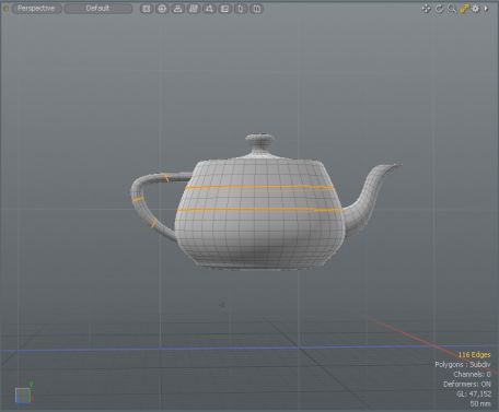
| 4. | Under the layout menu, select Edges. |

| 5. | On the top-right of the interface, click the Selection Sets |
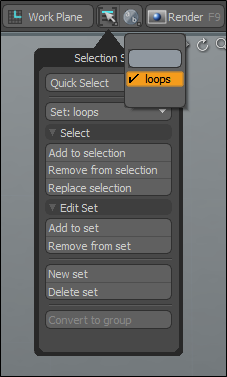
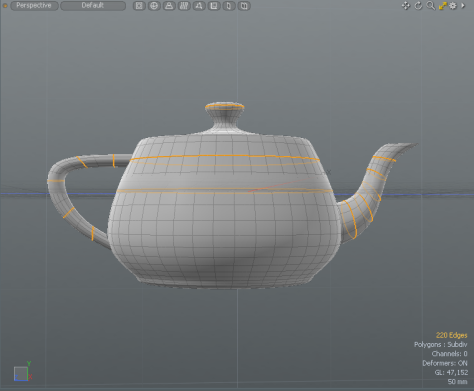
The edge selection set is displayed in the 3D viewport.
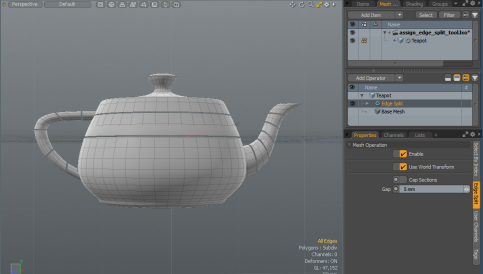
| 6. | On the right panel, open the Mesh Ops tab, and click Add Operator. |
| 7. | Double-click Mesh Operations > Edges > Edge Split. |
| 8. | On the right panel, open the Edge Split tab and set Gap to 5mm and click Return. |
Applying the Edge Split Tool using the Schematic Viewport
Using the procedural Edge Split tool in the Schematic viewport allows you to select a set of edges and split the mesh in two or more patches. You can interactively update the Gap distance by changing the value.
Example
| 1. | Download our example scenes and unpack the files. |
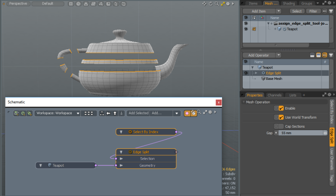
| 2. | In Model layout, load assign_edge_split_tool_schematic.lxo. |
| 3. | On the top-left corner of the interface, click the schematic palette |
![]()
| 4. | On the right panel, drag-and-drop Teapot onto the Schematic viewport. |
| 5. | On the top-right of the interface, click the Selection Sets |
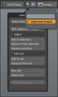
The edge selection set is displayed in the 3D viewport.
| 6. | In the Schematic viewport, click Add..., and double-click Mesh Operations > Edges > Edge Split. |
| 7. | In the Schematic viewport, click in the view area, and then select Edge Split. |
| 8. | On the right panel, open the Edge Split tab, set Gap to 55mm and press Return. |
The selection set is split at the edges.
Procedural Edge Split Properties
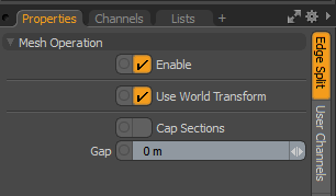
• Enable - Enables or disables the Edge Split tool
• Use World Transform - Sets the coordinates from Model Space to World Space where vertices are defined relative to an origin common to all the objects in a scene.
• Caps Sections- Creates extremities when the mesh is totally cut in two (or more) parts.
• Gap- Specifies the distance to split the mesh at the selected edges.
Grow Quads
The Grow Quads command extends a row of quad polygon along a selected edge border.
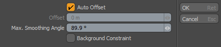
• Auto Offset - Attempts to match preceding row's size, or disable to set a specific offset value.
• Offset - Specifies distance of offset.
• Max. Smoothing Angle - Specifies maximum smoothing for newly created polygons across angular surfaces.
• Background Constraint - When enabled, the tool uses a background mesh to constrain the operation.
Note: For more information on using Background Constraints, see Constrain to Background.
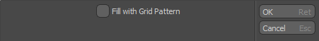
Fill Quads
The Fill Quads command attempts to fill any open holes within a mesh with only quad polygons. You first need to define the area to fill with an edge selection that outlines the target. When the command is invoked the dialog below. There are two possible options, pressing OK and accepting the default uses the least number of polygons to fill the area. Enabling the Fill with Grid Pattern option fills the target area with an even grid of polygons. However, this option also requires the edge selection to have an even number of edges for both its width and height. This option detects corners and properly fills the area with a grid of quad polygons, even when an entire side of the selection area is left open, such as near an outer edge of a plane.
Sorry you didn't find this helpful
Why wasn't this helpful? (check all that apply)
Thanks for your feedback.
If you can't find what you're looking for or you have a workflow question, please try Foundry Support.
If you have any thoughts on how we can improve our learning content, please email the Documentation team using the button below.
Thanks for taking time to give us feedback.