Search is based on keyword.
Ex: "Procedures"
Do not search with natural language
Ex: "How do I write a new procedure?"
Edges to Curves
The Edges to Curves mesh operation lets you create multiple Spline curves, Polylines, Bezier curves, or B-spline curves from edges on an existing mesh, selected through selection operators.
Using Edges to Curves
Before adding the Edges to Curves mesh operation, add a mesh to your scene. You can do this in the Mesh Ops tab, in the Mesh Operations list, or add a mesh with the traditional modeling tools.
Once you've added a mesh, follow these steps:
| 1. | Under the layout menu, click Edges, and select multiple edges on your mesh item. |
| 2. | On the right panel, open the Mesh Ops tab, click Add Operator, and under Mesh Operations > Edge, double-click Edges to Curves. |
| 3. | Expand the Edges to Curves item in the stack to reveal its Selection input. |
| 4. | Click (Add Selection), and in the Preset Browser, under New, double-click Select by Border. |
This selects the border edges of your mesh and applies the Edges to Curves operation to them.
Note: Alternatively, you can choose the Select by Index selection type, and in Edges selection mode, define your selection in the 3D viewport, or edit the Properties of the selection operation. For more information on selection types, see Procedural Selection.
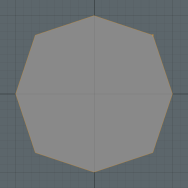
The Edges to Curves operation uses a polyline curve type by default, but you can change this in the Properties panel. In addition to Polyline, you can select Spline, Bezier, or B-Spline curve types:
|
|
|
|
|
|
Polyline Curve Type |
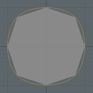
Spline Curve Type |
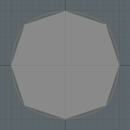
Bezier Curve Type |
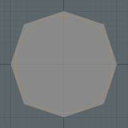
B-Spline Curve Type |
Creating Edges from Multiple Curves
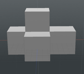
The Edges to Curves tool supports multiple curves. In this simple example, we will walk through the process of applying this tool to a set of edges and rendering the output.
| 1. | Using the Model layout, Ctrl/Cmd + click the cube |
| 2. | Under the layout menu, click Polygons, and select one polygon on the cube. |
| 3. | On the left panel, open the Mesh Edit tab, and click Bevel. |
| 4. | Click-and-drag the bevel handle to extend the polygon outwards. |
| 5. | Press the Spacebar and repeat the previous step to create a mesh item similar to this one. |
| 6. | Under the layout menu, click Edges, hold Shift , and select multiple edges on the mesh item. |
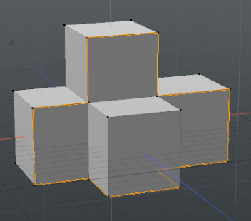
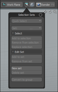
| 7. | Under the layout menu, click the selection set icon, click New set, and name it edges. |
| 8. | On the right panel, open the Mesh Ops tab, click Add Operator, and double-click Mesh Operations > Edge > Edges to Curves. |
| 9. | On the right panel, expand Edges to Curves, and click (Add Selection). |
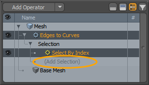
| 10. | Double-click Mesh Operations > Selection > Select By Selection Set. |
| 11. | In the bottom right panel, on the Section By Selection Set tab, type edges into the Name field, and press Enter. |
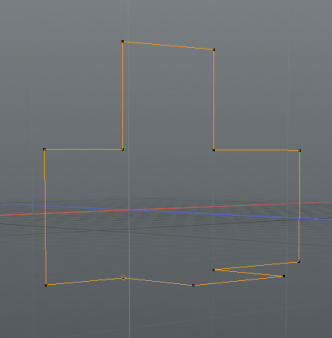
Your selected edges are converted into curves.
| 12. | Under the layout menu, click the selection set |
| 13. | Press Ctrl/Cmd + C to copy the curves. |
| 14. | On the Mesh Ops tab click Add Item, and click Mesh. |
| 15. | Press Ctrl/Cmd V to paste the curves into your new mesh layer. |
| 16. | On the Mesh Ops tab, expand Mesh and click the visibility |
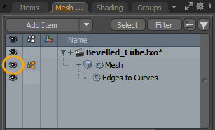
Tip: Notice that you see a point for every joint position on the curve. You can use these points to reshape your curve. Activate the Vertices selection mode, select a vertex, press W, and move the handle to reposition.
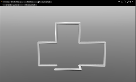
| 17. | On the right panel, select the mesh item, open the Curves tab, and enable Render Curves. |
Edges To Curves Properties
| Delete Geometry | Delete all non-curve geometry from the mesh. |
|
Curve Type |
Select the type of curve you would like to use. The following options are available: • Polyline - This option works well with the Pen Generator tool. • Spline Curve - Smoothed curve that works well with the Path Generator tool. Also matches subdivision surfaces more closely. • Bezier Curve - Linear curve that works with the Path Generator, but matches cage edges more closely. • B-Spline Curve - This type of curve works well with Catmull-Clark subdivision surfaces. |
|
Curve Mode |
Select the curve mode. The following options are available: • Single Curve - Creates a single curve running through the edges you've selected. This only works with edge selections that have a distinct start and end point, or closed loops. Overlapping edge selections, branching, and multiple edge loops are currently not supported. • Curve Per Edge - Creates a two point curve along each selected edge. This has no limitations about what can be selected, but it does not create a continuous curve, so it doesn't work well with things like the Sweep Effector or Path Constraints. |
|
Bezier Tangent Weight |
This option is only available if the Curve Type is set to Bezier Curve. In addition to having points for each point of the edges you've selected, a Bezier Curve has two surrounding control points, which define how the curve enters and exits the point. The further the control points are from that middle point where the curve goes through, the more the curve heads in the direction of the control point before it bends back towards the next point in its path. The Bezier Tangent Weight option controls how close or far those control points are from the middle point that the curve is passing through. At 0%, you get straight lines between points, and at 100% you get a more rounded curve. |
Using Edges to Curves in the Schematic
Once you have a mesh in your scene, you can add the Edges to Curves mesh operation to it, using the Schematic viewport.
| 1. | On the top left corner of the interface, click the Schematic palette |
![]()
| 2. | In the Schematic viewport, click Add..., and double-click Mesh Operations > Edge > Edges to Curves. |
The mesh operation is added to your scene, and automatically gets connected to your mesh item in the Schematic.
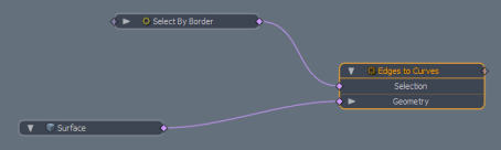
| 3. | To define the selection for the Edges to Curves operation, click Add..., and select Mesh Operations > Selection > Select By Border. |
| 4. | Connect the Select By Border operation to the Selection input of the Edges to Curves node. |
Sorry you didn't find this helpful
Why wasn't this helpful? (check all that apply)
Thanks for your feedback.
If you can't find what you're looking for or you have a workflow question, please try Foundry Support.
If you have any thoughts on how we can improve our learning content, please email the Documentation team using the button below.
Thanks for taking time to give us feedback.