Search is based on keyword.
Ex: "Procedures"
Do not search with natural language
Ex: "How do I write a new procedure?"
Cylinder Falloff
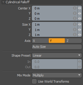
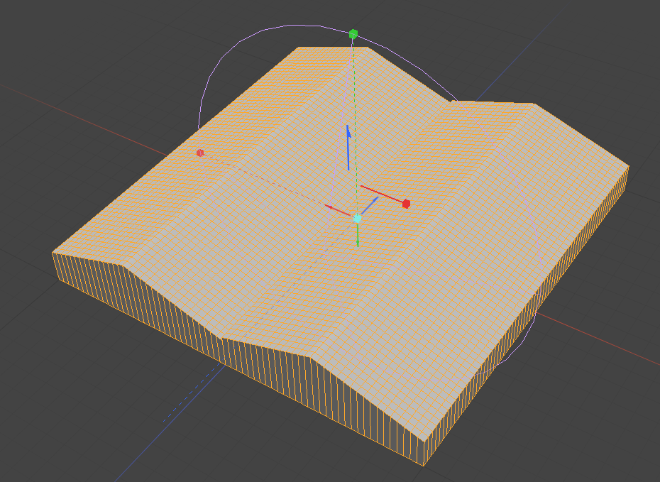
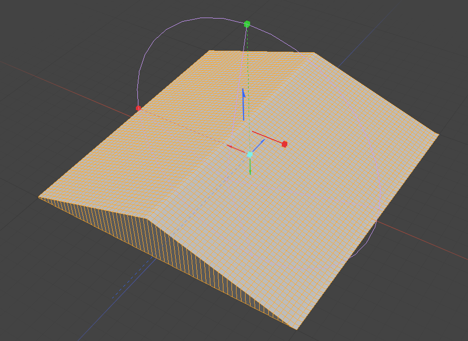
The Cylinder Falloff creates a circular falloff that extends across the length of a virtual cylinder. All vertices at the center of the cylinder receive 100% of the tool's influence, attenuated toward the outer edge and beyond the cylinder, where vertices receive none of the tool's influence.
|
Center X/Y/Z |
Defines the center of influence, where the strength of the falloff is greatest (100%). The strength of the falloff attenuates toward the outer bounds of the cylinder. The falloff volume extends upward and downward toward infinity. |
||||
|
Size X/Y/Z |
Defines the radius of a perfect circle from the center and determines the outer area of the falloff where there is no effect. |
||||
|
Axis |
Defines the projection axis for the cylinder, determining the direction for the falloff. |
||||
|
Auto Size |
You can select this option to automatically size the falloff's Center and Size values to match the bounding box of the current selection. |
||||
|
Shape Preset |
The strength of the falloff's influence can be controlled along the extent using a shape preset. • Linear - Attenuation of falloff occurs evenly across its range. • Ease-In - Strength of falloff is greater toward the Start position. • Ease-Out - Strength of falloff is greater toward the End position. • Smooth - Strength of falloff is greater toward the center of the falloff. • Custom - You can use the In/Out options to fine-tune strength of falloff. |
||||
|
In/Out |
The In value determines the strength of the falloff nearer to the Start position, and the Out value determines the strength on nearer the End side of the falloff. |
||||
|
Mix Mode |
In instances where there are multiple falloffs applied to a transform (by using the Add option of the Falloff menu), the mix mode defines how each falloff interacts with the other. |
||||
|
Use World Transforms |
By default, falloffs calculate their influence over transforming vertices according to their relative position, using object space vertex positions. When this option is enabled, all selected mesh surfaces are considered one surface and they deform as one.
|
Sorry you didn't find this helpful
Why wasn't this helpful? (check all that apply)
Thanks for your feedback.
If you can't find what you're looking for or you have a workflow question, please try Foundry Support.
If you have any thoughts on how we can improve our learning content, please email the Documentation team using the button below.
Thanks for taking time to give us feedback.