Effect - Texture Item
By default, any new material tag that you apply to a selection of polygons gains a Material item layer in the Shader Tree. Materials control the most common surface settings directly (such as Diffuse Color, Specular Amount, Reflection Amount, and Transparency). These settings are quite powerful on their own, but rendered surfaces that solely use the basic material settings can look flat or uninteresting. By adding texture layers (procedural or image-map based ones), you can achieve richer and more realistic surfaces.
Note: For information about adding and working with Shader Tree item layers, see the Shader Tree topic.
Once you add a layer, you can right-click the effect name for the layer (in the rightmost column) and direct how to have the texture affect the surface. Select a Category button to see additional samples.
Basic Channels
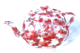
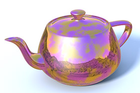
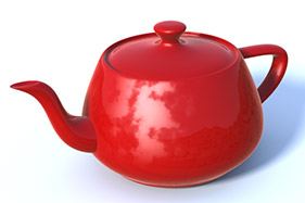
Clearcoat Amount
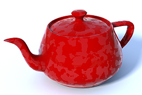
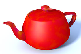
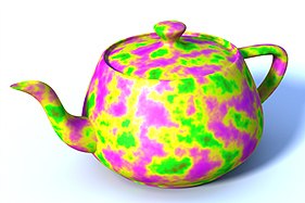
Adds an additional unblurred and untinted reflective layer to a surface to simplify the simulation of multiple layers of paint (especially automotive). When you set a texture layer to this effect, it controls the amount of Clearcoat across the surface. In the example, an additional Noise procedural texture with a high Gain value makes the result more apparent. With color image maps, Modo only uses the brightness (luminosity) of the image.
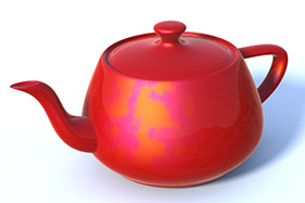
Diffuse Amount
Acts as a multiplier with the Diffuse Color setting to represent how much light is reflected from the surface. In the real world, all objects absorb certain wavelengths of light while reflecting others. The light that is reflected is what you see as the color of the object. When you set a texture layer to control the Diffuse Amount, it darkens the color of the surface. The more light that is absorbed, the darker the surface appears. Controlling the Diffuse Amount is especially important for reflective surfaces. Reflections are an additive effect and otherwise would appear too bright. You can adjust this automatically by enabling Conserve Energy in the material item layer.
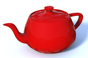
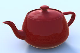
Diffuse Color
Determines the color of the surface when lit by sources of pure white light (whether directly or indirectly). This is represents the light that bounces from the surface and, effectively, is the color of the object.
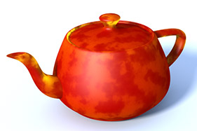
Diffuse Roughness

Simulates a microscopic roughness effect by modifying the standard shading model to produce a more realistic matte surface. Extremely matte surfaces (such as stone, concrete, or plaster) reflect light very differently than smooth or glossy surfaces (such as glass or plastic). This is because on a microscopic level the matte surface is actually quite rough and spreads the light outwards to make the surface appear flatter. Any texture layer set to Diffuse Roughness modulates the Diffuse Roughness amount. A black value in the texture equals a 0% value and attenuates toward white, which represents a 100% value. When using color image maps, Modo uses only the brightness (luminosity) of the image.
Dissolve
Fades out all surface settings together. The Dissolve effect is different from a Transparency effect. Transparency does not affect additive surface effects (such as Specular or Reflections), but Dissolve does. When you set any texture layer as Dissolve, the black areas are completely opaque and they attenuate toward white, which is completely transparent. When using color image maps, Modo uses only the brightness (luminosity) of the image.
Luminous Amount
Modulates the Luminosity setting of the Material item layer to control how much illumination radiates from the surface. (Illumination only contributes to scene shading when you enable Global Illumination.) A black value in the texture equals 0% and attenuates toward white, which represents 100%. When using color image maps, Modo uses only the brightness (luminosity) of the image.
Luminous Color
Controls the Luminous Color setting of the Material item layer to control the color of any illumination radiating from the surface. (Illumination only contributes to scene shading when you enable Global Illumination.)
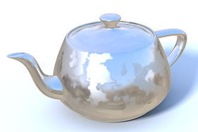
Reflection Amount
Modulates the Reflection Amount setting of the Material item layer to control how reflective (mirrored) a surface is. A black value in the texture equals 0% and attenuates toward white, which represents 100%. When using color image maps, Modo uses only the brightness (luminosity) of the image. In the rendering process, reflections are an additive process. To avoid reflections from becoming too bright, reduce the Diffuse Amount, which is the inverse of the Reflective Amount. Modo does this automatically if you enable Conserve Energy for the material item.
Reflection Color
Controls the Reflection Color setting of the Material item layer to control the color of any reflective areas of a surface.
Reflection Fresnel
Controls the Reflection Fresnel setting of the Material item layer to control the amount of any glancing angle (Fresnel) reflectivity. When using color image maps, Modo uses only the brightness (luminosity) of the image.
Refraction Roughness
Modulates the Refraction Roughness setting of the Material item layer to control how sharp or blurry refractions are through transparent surfaces. A black value in the texture equals 0% and attenuates toward white, which represents 100%. When using color image maps, Modo uses only the brightness (luminosity) of the image.
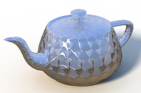
Roughness
Modulates the Roughness setting of the Material item layer to control the apparent roughness of a surface's specularity or reflectivity when you enable Blurry Reflection. The rougher the surface is, the more spread out the specular highlights are to simulate the look of microscopic bumps on a surface. A black value in the texture equals 0% and attenuates toward white, which represents 100%. When using color image maps, Modo uses only the brightness (luminosity) of the image.
Specular Amount
Modulates the Specular Amount setting of the Material item layer to controlling the specular reflection over a surface. Specularity is a simulation of a direct light source's reflection on a surface. A black value in the texture equals 0% and attenuates toward white, which represents 100%. When using color image maps, Modo uses only the brightness (luminosity) of the image.
Specular Color
Controls the Specular Color setting of the Material item layer to control the color of any specular reflections on a surface.
Specular Fresnel
Controls the Specular Fresnel setting of the Material item layer to control the amount of any glancing angle (Fresnel) specularity. A black value in the texture equals 0% and attenuates toward white, which represents 100%. When using color image maps, Modo uses only the brightness (luminosity) of the image.
Subsurface Amount
Modulates the Subsurface Amount setting of the Material item layer to controlling subsurface scattering on a surface. This is the simulation of light bouncing around inside a surface before exiting. A black value in the texture equals 0% and attenuates toward white, which represents 100%. When using color image maps, Modo uses only the brightness (luminosity) of the image.
Subsurface Color
Controls the Subsurface Color setting of the Material item layer to control the color of any subsurface scattering on a surface.
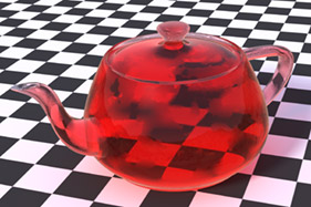
Transparent Amount

Modulates the Transparency setting of the Material item layer to control how clear (or see through) a surface is. A black value in the texture equals 0% and attenuates toward white, which represents 100%. When using color image maps, Modo uses only the brightness (luminosity) of the image. Transparency does not remove additive effects (such as Specularity and Reflectivity). In cases where this is necessary, use the Dissolve or Stencil effects.
Transparent Color
Modulates the Transparent Color setting of the surface. Some transparency needs to be present to see its effect on the surface. (Using an image map texture produces a result similar to a projector transparency slide where the image is clearly visible but completely transparent.)
Cel Edge Material Channels
Edge Width
Modulates the Edge Width value of the Cel Edges texture layer.
Edge Color

Determines the Edge Color of the Cel Edges texture layer.
Hair Material Channels
Glints Color: Determines the Glints Color of the Hair Material texture layer.
Primary Highlight Color: Determines the Primary Highlights Color of the Hair Material texture layer.
Rimlight Color: Determines the Rimlight Color of the Hair Material texture layer.
Secondary Highlight Color: Determines the Secondary Highlight Color of the Hair Material texture layer.
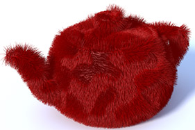
Fur Bump
Controls the Flex direction for fur growth. Generally, as fur grows, it bends toward the ground, which by default is negative Y (assuming this is the direction that gravity pulls the fibers). This is similar in function to Fur Direction, but Fur Direction requires a 32-bit image map for combing. Fur Bump angles the fiber direction similar to how a bump map perturbs the surface rays. Then you can use arbitrary texture layers (such as image maps and procedural textures) to control the fur's direction. The fur item's Fur Bump Amplitude setting controls the strength of the Fur Bump effect.
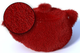
Fur Clump Density
Modulates the fur Clumps setting of the fur item layer to control the strength of how tightly clumps of fur gather together. A black value in the texture equals 0% and attenuates toward white, which represents 100%. When using color image maps, Modo uses only the brightness (luminosity) of the image.
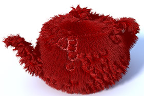
Fur Clumps
Determines whether or not fur clumps together. Clumped fur uses the strength value of the Clump input field for clumping areas attenuating toward no clumping. The results of Clumps and Clump Density are similar. The difference is that Clumps Density controls the strength of the clumping, and Clumps controls whether or not a fiber clumps. A black value in the texture equals 0% and attenuates toward white, which represents 100%. When using color image maps, Modo uses only the brightness (luminosity) of the image.
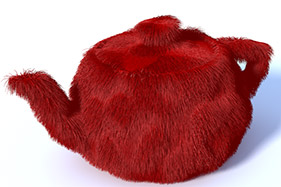
Fur Curls
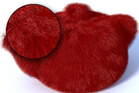
Modulates the fur Curls setting of the fur item layer that controls the strength of the corkscrew curls added to each individual fiber. This layer may require additional segments to properly render the curly fur. A black value in the texture equals 0% and attenuates toward white, which represents 100%. When using color image maps, Modo uses only the brightness (luminosity) of the image.
Fur Density
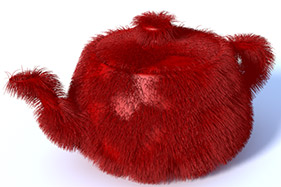
Modulates the Render Density setting of the fur item layer that controls the thickness of the fur (number of fibers). A black value in the texture equals 0% and attenuates toward white, which represents 100%. When using color image maps, Modo uses only the brightness (luminosity) of the image.
Fur Direction
Controls the Flex direction of the fur item layer. Generally, as fur grows, it bends toward the ground, which by default is negative Y (assuming this is the direction gravity pulls the fibers). The Fur Direction effect requires a 32-bit HDR image format( such as EXR) and is similar to Vector Displacement. You can create this type of image in Modo by using Add Fur Direction Texture (for more information, see Adding Images). Once you create and apply the basic image, you can use the styling tools of the Paint tab to control the direction of the fiber's growth independent of other settings. Make sure to enable Edit Fur Map of the styling tools when sculpting fur this way. To control both Growth Direction and Length, use the Fur Vector setting.
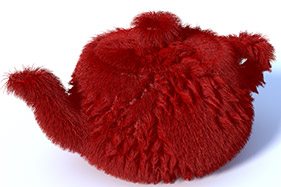
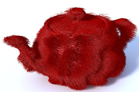
Fur Flex
Modulates the Flex setting of the fur item layer to control the amount of bend applied to individual fibers. A black value in the texture equals 0% and attenuates toward white, which represents 100%. When using color image maps, Modo uses only the brightness (luminosity) of the image.
Fur Growth Jitter
Modulates the Growth Jitter setting of the fur item layer to control how uniform or random the fiber growth is. A black value in the texture equals 0% and attenuates toward white, which represents 100%.
Fur Length

Modulates the Length setting of the fur item layer as a percentage of the total length. A black value in the texture equals 0% and attenuates toward white, which represents 100%. When using color image maps, Modo uses only the brightness (luminosity) of the image.
Fur Root Bend
Modulates the Fur Root Bend setting of the fur item layer, which controls the angle at which the fiber grows from the polygon surface. A black value in the texture equals 0% and attenuates toward white, which represents 100%.
Fur Vector
There are two ways to style fur surfaces in Modo. Guides are the most common as they are easy to visualize and control. You can use 32-bit HDR images as such (much like those meant for Vector Displacement). You can apply an HDR image to the Shader Tree and assign the Fur Vector effect, which is effective for shorter fur type surfaces than longer, styled hair. You can create this type of image in Modo by using the Add Fur Direction Texture option (for more information, see Adding Images). Then, use the styling tools of the Sculpting tab to interactively control various properties of the fur. Make sure to enable Edit Fur Map of the styling tools when sculpting fur this way.
Shader Control
Driver A, B, C, and D
Controls a Gradient layer by using one or more texture layers set to the same drive letter (A, B, C, or D). Modo feeds the values of the layer(s) into any gradient item layer with a matching input parameter. Within the gradient, you may apply colors or values based on the values of the input textures. This is useful to remap the shades of an image map texture or to achieve finer control beyond the Bias and Gain settings in any procedural texture.
Group Mask
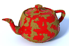
Masks the effect of all layers within a given Group Item. Due to the layered nature of the Shader Tree, this reveals any lower Shader Tree layers. Using multiple tags applied to multiple group items produces some interesting effects. The example masks a group item that has a displacement layer and a gradient layer that simulates a muddy look.
Layer Mask
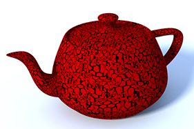
Masks the effect of any layer directly above it in the Shader Tree. You can drop any texture or procedural layer onto another layer to automatically set it as a layer mask. With this, you can individually mask the contribution of a single layer in the Shader Tree. The example adds a Grid texture layer that is masked by the Noise procedural layer, which is set to Layer Mask, directly below it in the Shader Tree.
Texture Offset
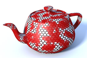
Displaces the values of one layer with another (defined as the Texture Offset). (This is like a Vector Displacement, but for textures instead of surfaces.) The Texture Offset layer modulates any and all layers above it in the Shader Tree within the same material group mask. (Make sure you don't place any texture layers above it that you don't want distorted.) Textures can be either grayscale or RGB layers. RGB layers produce a more complex offset effect with the additional channel information for multi-directional offset. (This is similar to how RGB values work for Vector Displacement.) The example adds a standard Noise texture layer as an offset to a hexagon grid pattern. The Texture Offset Amplitude setting of the Texture Locator controls the strength of the offset. You can adjust this further by modifying the texture layer's Opacity setting.
Special Effects
Anisotropy Direction
Even on very smooth surfaces, microscopic scratches affect the way lights reflect across them. Their effect is most apparent through the reflection and specular attributes drawing them out in a parallel direction to the scratches. Surfaces that are direction dependent are considered anisotropic. It is especially apparent on machined surfaces (such as brushed metals), but this is also visible on many fabrics (such as silks and carbon fiber). Anisotropic maps require a special RGB setup for proper results. To make your own anisotropic maps, see the Anisotropic Direction topic.
RGBA
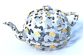
Makes only the opaque areas of the image visible on the surface when you set a texture layer to RGBA and use an image with embedded transparency (such as a TGA or PNG file). All other areas of the surface are invisible — including the associated attributes (such as Specular and Reflections). You can define both opacity for a surface and the diffuse color with a single texture layer. This is similar to having an image for Diffuse Color and then another Alpha image set to Stencil. This effect is not appropriate if you need variable transparency.
Stencil
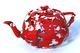
Truncates all surface settings together. Stencil is different from 'Transparency. (Transparency does not affect additive surface effects, such as Specular or Reflections, but Stencil does.) Stencil's concept is identical to Dissolve's, but Stencil does not allow for gray shades between black and white, so it always produces a hard edge. Because of this, it is also much faster to compute to provide faster results when many transparent surfaces overlap (such as leaves in a tree).
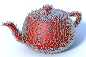
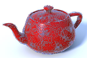
Surface Particle
Surface Particle Density
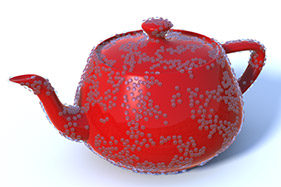
Controls the distribution of replicas procedurally by using a texture layer when using Replicators and Surface Generators to duplicate geometry over the surface of an object (for example, to make grass or water droplets). The texture layer attenuates the total density as defined by the Minimum and Average spacing options of the Surface Generator. A black value in the texture equals 0% and attenuates toward white, which represents 100%. When using color image maps, Modo uses only the brightness (luminosity) of the image.
Surface Particle Normal
Controls the normal direction of replicas procedurally as an offset from the surface normal when using Replicators and Surface Generators to duplicate geometry over the surface of an object (for example, to make grass or water droplets).
Surface Particle Size
Controls the scaling of replicas procedurally by using a texture layer when using Replicators and Surface Generators to duplicate geometry over the surface of an object (for example, to make grass or water droplets). The texture layer sizes the replica as a percentage of the default object size. A black value in the texture equals 0% and attenuates toward white, which represents 100%. When using color image maps, Modo uses only the brightness (luminosity) of the image.
Surface Shading
Bump
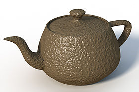
Simulates small surface details that would be difficult or impossible to model directly. Bump maps are similar to displacement maps; however, they do not displace the geometric surface itself, but only the rays that hit it. In extreme cases this weakness shows on silhouette edges. Because of this, keep bump mapping to smaller details that wouldn't be noticeable at glancing angles. because bump maps do not require additional geometry, they render quickly. Bump maps require a grayscale image or a procedural layer. When you apply color images and set the layer as Bump, Modo uses only the brightness (luminosity) of the image.
Displacement
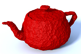
Adds detail to a surface (like a Bump map). When using Modo's sculpting tools (or an external application such as ZBrush™ or Mudbox™), displacement maps can provide an organic method of modeling. Displacement maps use the micropolygon tessellation feature of Modo to create additional geometry on subdivision surface models. The displacement map moves the surface a given distance along its normal defined by the Displacement Distance setting of the material item and the gray shades of the texture layer, itself. This results in a model with greater surface detail and a more organic form that is easier to obtain. Often, a displacement map has a gray middle ground with the dark values pushing the surface in and white values pushing the surface out. You achieve this by setting a inverse (negative) value for the Low setting of the image map layer's property or by setting a negative value in a procedural texture.
Affects the shading normal of the surface to provide a way to simulate high-resolution detail on a low-resolution polygon model. Normal maps are generally generated through by baking, in which Modo projects the surface detailing of a high-resolution model onto a low-resolution model and maps the resulting image onto it. At render time the low-resolution model look much like the high-resolution version at a much lower processor use. This is a popular method for generating geometry for realtime environments (such as games and simulations). For a normal map to render properly, you must use a UV map.
When you set the texture Effect to Normal type you may see a dialog asking, "Warning: Normal clip is using a color correction, do you want to set it to none?". By default, Modo uses sRGB color correction for all clips. In most cases this works well, however, it is usually not correct if the clip is being used as a normal map. And so the dialog allows you to choose whether to use color correction for the normal map. The dialog has the following options:
• Yes - Convert the current clip to (none) color space.
• No - Don't convert, accept the image's color space.
• Yes to All - Always convert to (none) color space, until Modo quits.
• No to All - Always don't convert to (none) color space, until Modo quits.
• Cancel - Don't use this feature. Equivalent to No to All.
Note: The settings are reset when you relaunch Modo.
Note: You can change the default colorspaces in the Color Management.
Object Normal
Object Normal maps are typically used in Games workflows for static, non-deforming objects (environment, props, and so on) to render quickly in game engines.
Standard normal maps encode the direction of the surface relative to the tangents of the surface. For example, they describe the surface as it would appear to an ant standing on the surface. Modo encodes the normals relative to the surface tangents. This means, Object Normal maps encode the direction in absolute terms in object space. For example, pure green means the surface is pointing straight up along the object's Y axis.
To set the texture Effect to Object Normal, in the Shader Tree, right-click on the Effect column for a material and select Surface Shading > Object Normal. The baking procedure is the same as Normal texture effect. For more information, see Bake from Object to Selected Texture.
Vector Displacement
Sculpts very highly detailed forms simply. Vector Displacement is similar to displacement mapping that pushes micro polygons outward along their normal a given distance. Displacement maps are only capable of moving a polygon in a single forward direction, but a vector displacement value can record all three directional values to the image map. With this, a Vector Displacement can produce overhangs and undercuts to a sculpted surface. To store the necessary information, a Vector Displacement requires an HDR image format (such as EXR).
Volumetrics
• Volume Sample Density: Determines the density value of the volume itself. This value is evaluated when sampling along the ray of a given 3D volume. The ray is used to calculate the overall density of the volume. This option should be used as an input parameter for a Gradient.
• Volumetric Absorption Amount: A scale value to define how much light energy is absorbed by the volume.
• Volumetric Absorption Color: Determines the color of the light that is absorbed by the volume.
• Volumetric Ambient Color: Determines a constant color value for the display of a volume.
• Volumetric Density:
The density value of the hypertexture. Like a 2D texture used on a surface, a hypertexture is a 3D texture used on a volume.
Volumetric Density is the base material density value. When the volume is rendered, samples are collected along the ray when the ray intersects a volume. This is a process called Ray Marching. The rays are broken into small steps and for each step along the way, it collects a volume sample. The Volume Sample Density is then multiplied by the Volumetric Density effect, which is controlled by the Volumetric part of the material. When all samples have been computed, the ray is flattened to produce a single scattering and absorption pair for the ray.
• Volumetric Level: Determines the offset of the Volume Sample Density value. The default value is 1.0.
• Volumetric Luminosity Amount: Determines the scale value to control how much light energy is emitted from the volume. This option is used for self-luminous objects.
• Volumetric Luminosity Color: Determines the color of the light that is emitted from the volume. This option is used for self-luminous objects.
• Volumetrics Scattering Amount: Specifies the scale value to control how much light energy is scattered from the volume. When set to a smaller value, the scattered energy is less.
• Volumetrics Scattering Color: Determines the color of the light that is scattered from the volume.
Volumetric Examples
The following procedures outline how to create Volumetric samples using the above parameters. Each sample is built on top of the previous sample.
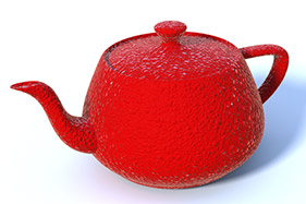
Creating a Volume Sample Density Sample
| 1. | Click File > New and then open the Render layout. |
| 2. | Add a volume to your scene. On the right-hand side pane, open the Item List, click Add Item, select Volumes and then double-click on Volume. |
A volume is added to your scene. In addition, by default, a Directional Light and an Environment Material are also added to your scene.
| 3. | In the Shader Tree, expand Environments > Environment, and toggle the eye button ( |
| 4. | In the Shader Tree, click Add Layer, and select Processing > Gradient. |
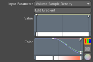
| 5. | In the Gradient Effect column, click the down arrow, and select Volumetric Effects > Volume Sample Density. |
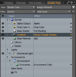
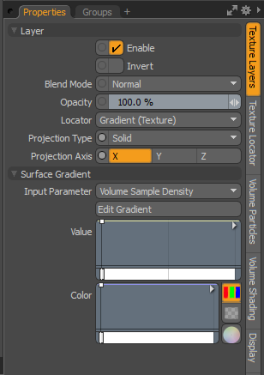
| 6. | In the Properties panel, open the Texture Layers tab, expand Surface Gradient, and then set the Input Parameter to Volume Sample Density. |
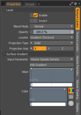
The Render viewport displays something similar to the following.
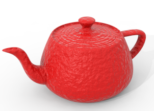
Creating a Volumetric Density Sample
Continue using the same scene.
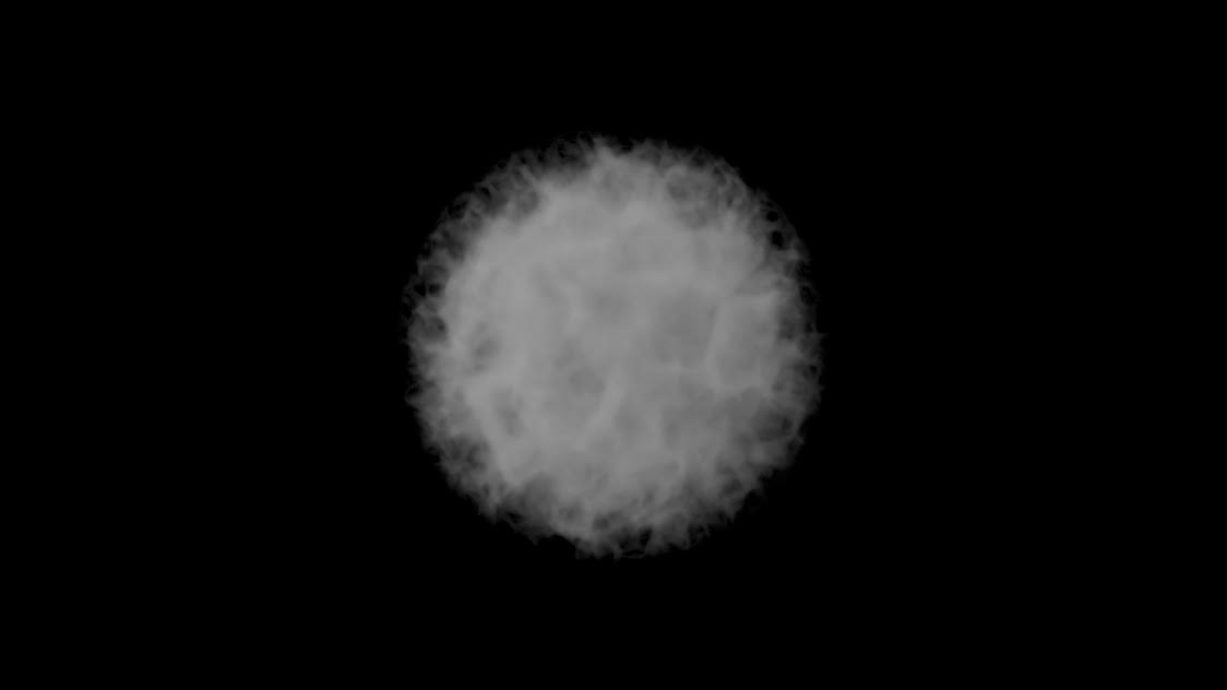
| 1. | In the Shader Tree, click Add Layer, and select Textures > Cellular. |
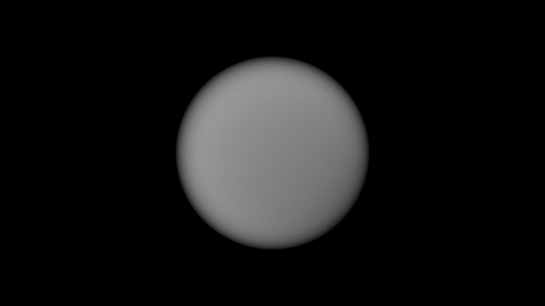
| 2. | In the Shader Tree, under the Effect column, click the down-arrow, and set Cellular to Volumetrics Effects > Volumetric Density. |
The Render viewport displays something similar to the following.
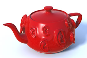
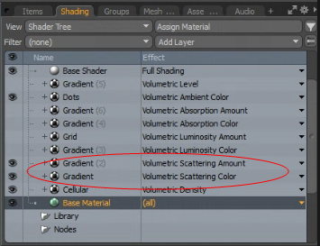
Creating a Volumetric Scattering Color Sample
Continue using the same scene.
| 1. | With the Gradient texture selected, click the down arrow in the Effect column, and select Volumetrics Effects > Volumetrics Scattering Color. |
| 2. | Next, change the color of the Gradient texture. In the Properties panel, open the Texture Layers tab, and then expand Surface Gradient properties. |
| 3. | In the Color graph, select a key frame, and then click the Color Picker icon. For more information about how to use the Color Picker, see Color Picker Viewport. |
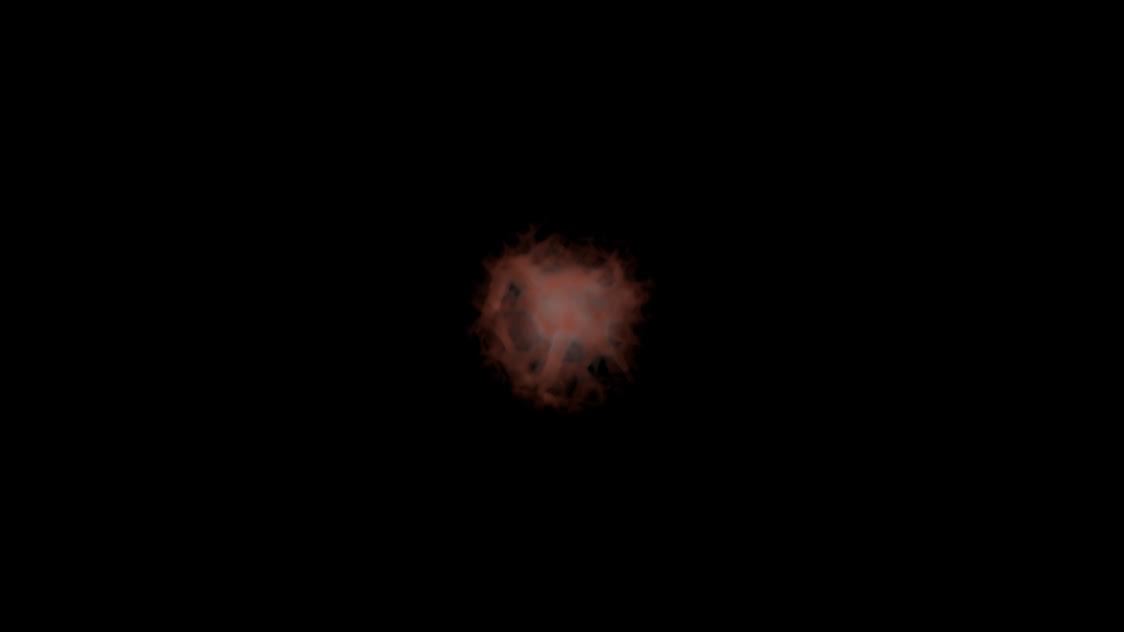
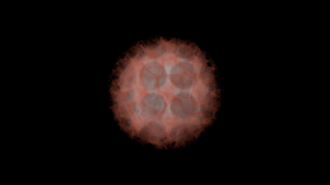
| 4. | Set the Volumetric Scattering Color to red. |
The Render viewport displays something similar to the following.

Creating a Volumetric Scattering Amount Sample
Continue using the same scene.
| 1. | In the Shader Tree, click Add Layer, and select Processing > Gradient. |
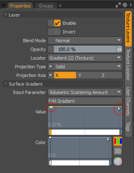
| 2. | In the Gradient Effect column, click the down arrow and select Volumetric Effects > Volume Scattering Amount. |
| 3. | In the Properties panel, open the Texture Layers tab and set the Surface Gradient > Input Parameter to Volume Scattering Amount. |
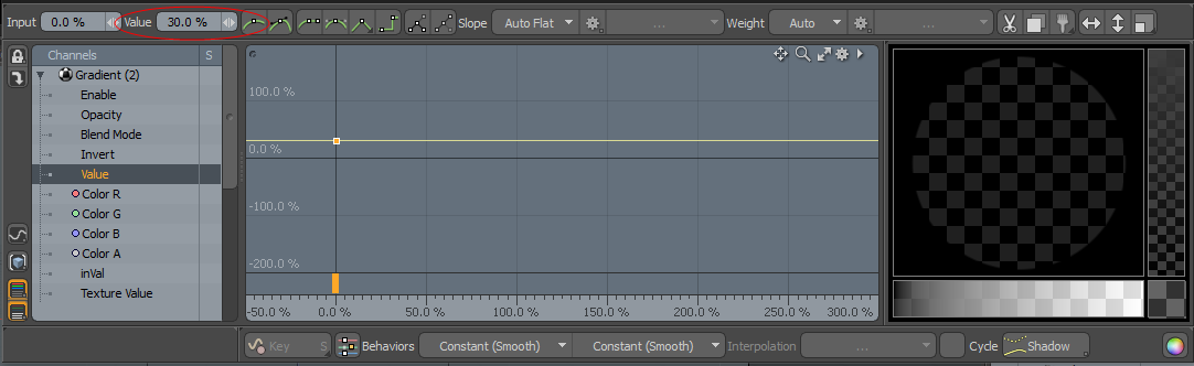
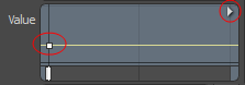
| 4. | In the Value graph, select a frame, and then click the arrow on the right, and click Open in Editor. |
| 5. | In the top left side of the Gradient Editor dialog, in the Value field, type 30%. |
The Render viewport displays something similar to the following.

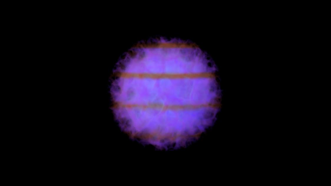
Creating a Volumetric Luminosity Color Sample
Continue using the same scene.
| 1. | In the Shader Tree, click Add Layer, and select Processing > Gradient. |
| 2. | In the Gradient Effect column, click the down arrow and select Volumetric Effects > Volumetric Luminosity Color. |
| 3. | In the Properties panel, open the Texture Layers tab, under Surface Gradient, set Input Parameter to Volumetric Scattering Amount. |
| 4. | In the Color graph, select a frame and then click the Color Picker. |
| 5. | Set the color to Blue. |
| 6. | In the Shader Tree, select the Base Material. |
| 7. | In the Properties panel, open the Material Rays tab. |
| 8. | Under Volumetrics, set Luminosity Amount to 100%. |
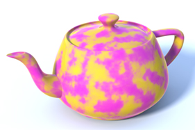
The Render viewport displays something similar to the following.

Notice, the volume is displayed in purple because the final energy is combined with Volumetric Scattering Color value.
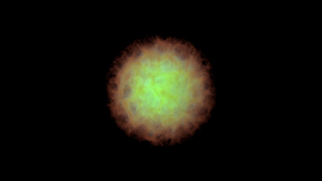
Creating a Volumetric Luminosity Amount Sample
Continue using the same scene.
| 1. | In the Shader Tree, click Add Layer, and select Textures > Grid. |
| 2. | With the Grid selected, under the Effect column, click the down arrow, and select Volumetric Effects > Volumetric Luminosity Amount. |
The Render viewport displays something similar to the following.
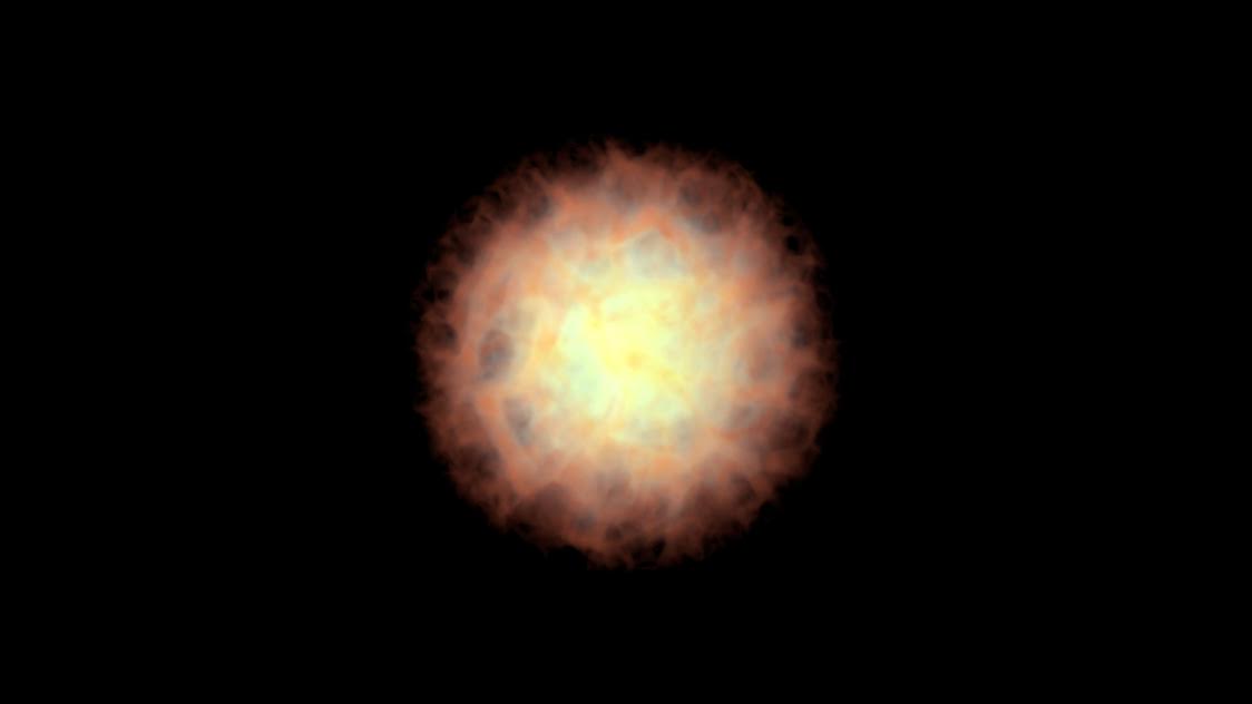
Creating a Volumetric Absorption Color Sample
Continue using the same scene.
| 1. | In the Shader Tree, toggle the eye button ( |
| 2. | In the Shader Tree, click Add Layer, and select Processing > Gradient. |
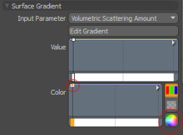
| 3. | In the Gradient Effect column, click the down arrow, and select Volumetric Effects > Volumetric Absorption Color. |
| 4. | In the Properties panel, open the Texture Layers tab, under Surface Gradient, set Input Parameter to Volumetric Sample Density. |
| 5. | On the Value graph, select a frame, and then click the arrow on the right, and select Open in Editor. |
| 6. | Set the Value field to 30% and the Input to 0%. |
| 7. | On the Color graph, select a frame, and then click the Color Picker. |
| 8. | Set the RGB values to 1.0, 0.0, 1.0. |

The Render viewport displays something similar to the following.
Creating a Volumetric Absorption Amount Sample
Continue using the same scene.
| 1. | In the Shader Tree, click Add Layer, and select Processing > Gradient. |
| 2. | In the Gradient Effect column, click the down arrow and select Volumetric Effects > Volumetric Absorption Amount. |
| 3. | In the Properties panel, open the Texture Layers tab, under Surface Gradient, set the Input Parameter to Volume Sample Density. |
| 4. | On the Value graph, select a frame, and click the arrow on the right, and select Open in Editor. |
| 5. | Set Value to 30% and Input to 0%. |
The Render viewport displays something similar to the following.
Creating a Volumetric Ambient Color Sample
Continue using the same scene.
| 1. | In the Shader Tree, turn the visibility off for all Gradients except the first two you created. |
| 2. | In the Item List, select Volume. |
| 3. | In the Properties panel, open the Volume Shading tab, expand Shading, and set the Ambient value to 1.0. |
| 4. | In the Shader Tree, click Add Layer and select Textures > Dots. |
| 5. | Set the Effect to Volumetric Ambient Color. |
| 6. | With Dots selected, in the Properties panel, open the Texture Layers tab. |
| 7. | Under the Layer properties, set the Projection Axis to Z. |
The Render viewport displays something similar to the following.
Creating a Volumetric Level Sample
Continue using the same scene.
| 1. | In the Shader Tree, hide the visibility of the Dots. |
| 2. | In the Shader Tree, click Add Layer, and select Processing > Gradient. |
| 3. | In the Gradient Effect column, click the down arrow, and select Volumetric Effects > Volumetric Level. |
| 4. | In the Properties panel, open the Texture Layers tab. |
| 5. | Under Surface Gradient, set the Input Parameter to Volumetric Level. |
| 6. | On the Value graph, select the frame and click the arrow on the right, and then select Open in Editor. |
| 7. | Set the Value to 50%. |
The Render viewport displays something similar to the following.