Slide / Edge Slide
The direct modeling Slide tool moves selected mesh elements (vertices, edges, and polygons) along their connected edges. There are three modes, Radial, Linear, and Face, which can be used depending on the style of selection and intended result. For more information, see Using Selection Modes , Sliding an Edge Using Linear Mode, Sliding a Vertex Using Linear Mode and Sliding a Vertex using Face Mode.
The procedural Edge Slide tool allows you to select the Radial mode to slide an entire edge loop to widen or narrow your selection, or use the Linear mode to specify the distance to move the selected geometry. For more information, see Applying the Procedural Slide Tool.
You can also use the Slide tool and the mesh operation on a UV map by selecting the appropriate UV map in the tool's properties.
Tip: For more information on direct and procedural modeling, see Modeling Techniques.
Activating the Tool
Note: Before applying this tool, you must activate a component selection mode. For more information, see Understanding Items vs. Components.
Direct Modeling Slide Tool:
• In the Model layout, activate the Vertices component selection mode. On the left panel, open the Vertex tab, and click Slide.
In the Model layout, activate the Edges component selection mode. On the left panel, open the Edge tab, and click Slide.
In the Model layout, activate the Polygons component selection mode, and press S.
• In the Topology layout, on the left panel, open the Tools tab, and click Edge Slide.
• On the menu bar, click Geometry > Slide.
• While using any component selection mode, press S.
Procedural Modeling Edge Slide Tool:
• In the Mesh Ops tab, click Add Operator, and double-click Mesh Operations > Edge > Edge Slide.
• In the Schematic view, click Add..., and double-click Mesh Operations > Edge > Edge Slide.
Using Selection Modes
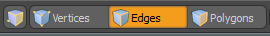
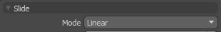
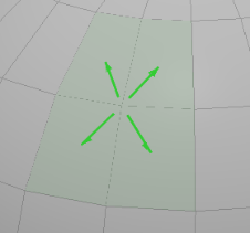
• In the Edges or Polygons selection mode, on the left panel, in the Slide properties, set Mode to Linear. The Slide tool displays the available slide vectors. When activated, Select Through is disabled by default.
![]()
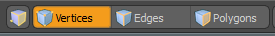
• When using the Vertices selection mode, on the left panel, in the Slide properties, set Mode to Linear.The Slide tool displays the available slide vectors. When activated, Select Through is enabled by default.
![]()
For more information about selection modes, see Selecting Items.
Sliding an Edge Using Linear Mode
| 1. | Click Edges and select an edge. |
Tip: Hold Shift and click to add more edges to the selection. You can select multiple edges by clicking and dragging or right-click lassoing.
| 2. | Press S to activate the Slide tool. |
Alternatively, on the left panel, open the Edge tab and click Slide.
| 3. | On the left panel, in the Slide properties, set Mode to Linear. |
| 4. | Click and drag on one of the handles to slide the edge(s) into a new position. |
![]()
| 5. | Press Esc to drop the tool. |
Sliding a Vertex Using Linear Mode
| 1. | Click Vertices and select a vertex on your mesh item. |
| 2. | Press S to activate the Slide tool. |
![]()
| 3. | On the left panel, in the Slide properties, set Mode to Linear. |
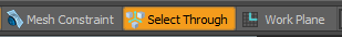
| 4. | Ensure that the Select Through button is enabled. |
| 5. | Click and drag on one of the handles. |
![]()
| 6. | Press the space key to drop the tool. |
| 7. | Hold Shift and select a number of additional vertices. |
| 8. | Press S and click and drag on a handle. |
![]()
| 9. | Press Esc to drop the tool. |
Sliding a Vertex using Face Mode
Face mode allows you to slide a vertex on connected faces.
| 1. | In Vertices selection mode, select a vertex and activate the Slide tool. |
The tool becomes active and the Tool Properties button appears on the left pane.
| 2. | Click the Tool Properties button and set Mode to Face. |
The handles in the 3D viewport change and you can see the connected polygons highlighted.
| 3. | Drag on a handle to slide the vertex on the respective face. |
Note: The vertex cannot go outside of the polygon when Stop at Edges is enabled.
| 4. | To adjust the tool's properties, see Direct Modeling - Slide Tool Properties. |
Applying the Procedural Slide Tool
The procedural Edge Slide tool allows you to select the Radial mode to slide an entire edge loop to widen or narrow your selection, or use the Linear mode to specify the distance to move the selected geometry. Specifying other properties allows you to position your selection exactly where you want it.
Example
| 1. | Download our example scenes and open Edge Slide meshop.lxo in the Model layout. |
| 2. | On the right panel, ensure that the model item is selected. |
| 3. | Under the layout menu, select Edges. |

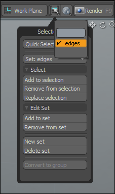
| 4. | On the top right of the interface, click the Selection Sets |
| 5. | On the right panel, open the Mesh Ops tab, and click Add Operator. |
| 6. | Double-click Mesh Operations > Edge > Edge Slide. |
| 7. | On the right panel, open the Edge Slide tab, and set the Mode to Linear. |
Tool handles appear in the 3D viewport.
| 8. | Drag the red (X) handle to slide your selection. |
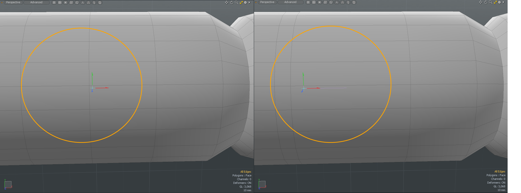
The Distance and Direction of the selected X, Y, or Z handles displays the absolute value in the Properties tab.
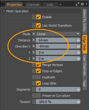
Note: Dragging the cyan center tool handle updates the Distance and Direction for X and Z only. 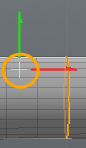
Procedural Edge Slide Properties
|
Mode |
• Allows you to specify one of the following modes: • Radial Mode - This is most useful for sliding entire edge loops such as widening or narrowing a selected edge loop around an eye. When this mode is active, the DirectionX, Y, and Z options are disabled as the only relevant input is Distance, which indicates how far to slide the selected loop between the next and previous loops. • Linear Mode - Provides a method to slide elements along intersecting edges. When this mode is enabled, the Direction X, Y, and Z options are activated. When interacting with the tool in a 3D viewport the direction of the handle determines the edge to slide along. • Face - This mode is not available in Procedural modeling. |
| Distance |
Allows the tool's numeric entry to be a specific distance based on the current unit system, so that geometry can be moved a specific number of feet, inches, meters, and so on. |
|
When this option is active, vertices are merged if the slide tool results in vertices sharing the exact same coordinates. For example, sliding an edge 100% with this option enabled results in that edge being merged into its neighbor. This can be particularly convenient when combined with the Stop at Edges option. |
|
| Stop at Edges | With this option active, the selected tool stops the slide when the selected mesh elements reach the surrounding edges. |
| Duplicate | When active, the Duplicate option creates a new edge rather than simply sliding the selected edge. With this option enabled, it is simple to create new edges or edge loops, and place them along the existing curve. |
| Loop Slide | When sliding an edge selection, Loop Slide constrains the movement along the existing polygonal bounds. |
| Segments | Adds extra edge loops between the original edge loop and duplicated edge loop. This option works with Duplicate option. |
| Preserve Curvature | When enabled, the new position is computed along a curve through the edges to maintain the overall curvature or surface continuity. Once enabled, the Tension setting becomes available, controlling the tightness of the curvature preservation. |
| Tension | Determines the strength of the curvature preservation. The default value of 100% calculates the curvature similar to a spline generated along the edge's length, placing the new vertex appropriately (a value of 0% disables the Preserve Curvature option). Negative values inset the curvature and higher values further offset the vertex out from the curve's position. |
| UV Map | Select a UV map to use Slide on a UV map. When set to (none), the tool works on 3D geometry. |
Applying the Slide Tool using the Schematic Viewport
Using the procedural Edge Slide tool in the Schematic viewport allows you to push the selected mesh elements along their connected edges.
Example
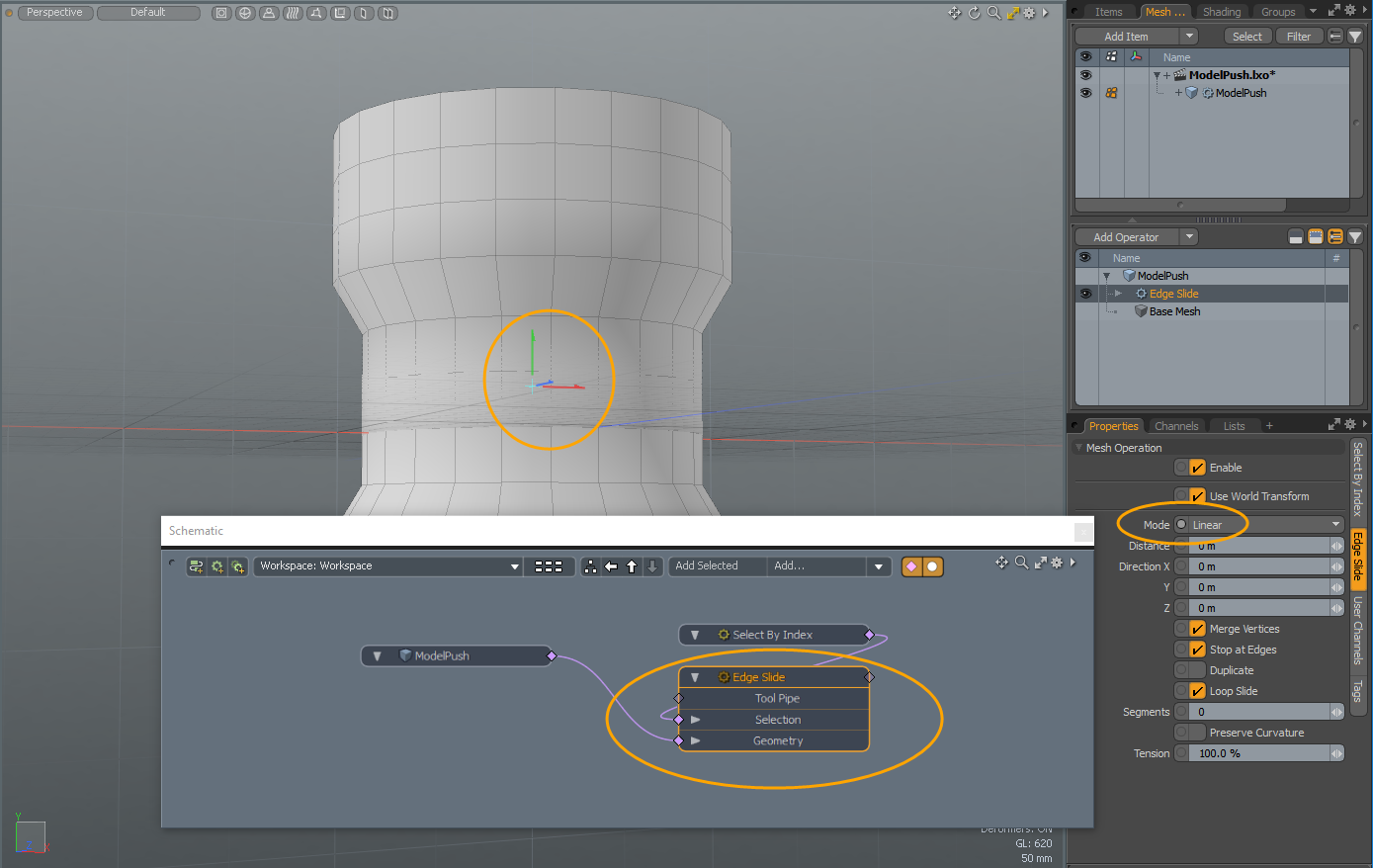
| 1. | Download our example scenes and open ModelPush.lxo in the Model layout. |
| 2. | On the top-left corner of the interface, click the schematic palette |
![]()
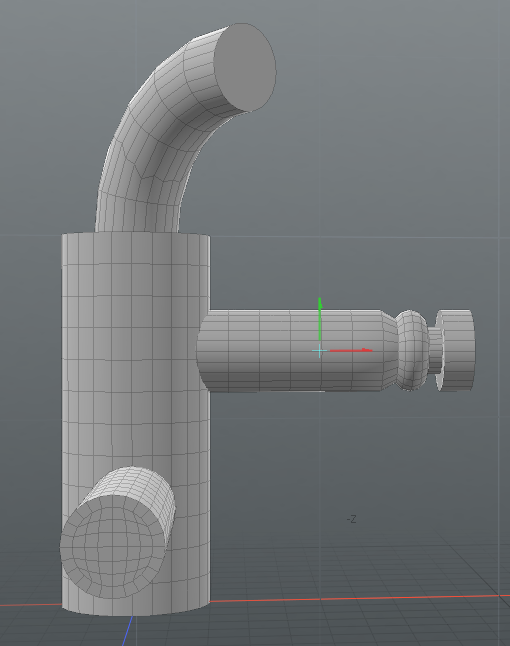
| 3. | On the right panel, drag-and-drop ModelPush onto the Schematic viewport. |
| 4. | Under the layout menu bar, click Edges. |
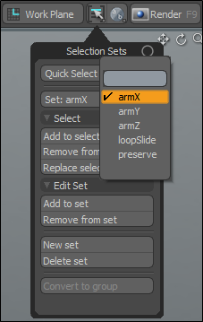
| 5. | On the top-right of the interface, click the Selection Sets |
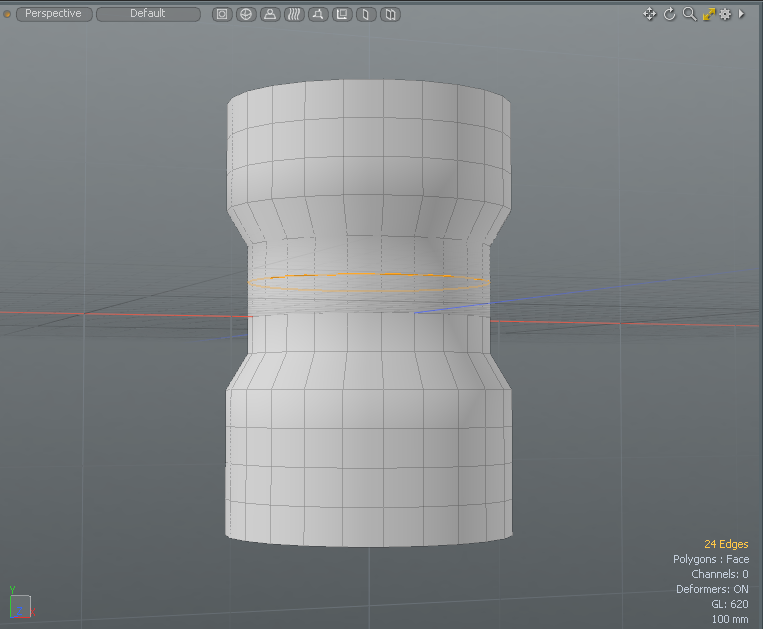
An edge selection is highlighted on the model in the 3D viewport.
| 6. | In the Schematic viewport, click Add..., and double-click Mesh Operations > Edge > Edge Slide. |
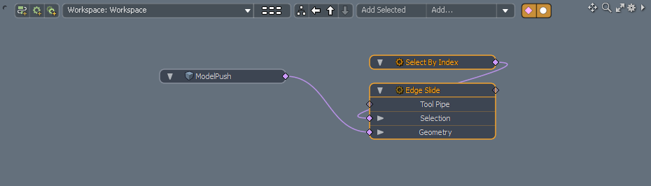
| 7. | In the Schematic viewport, click in the view area, and then select Edge Slide. |
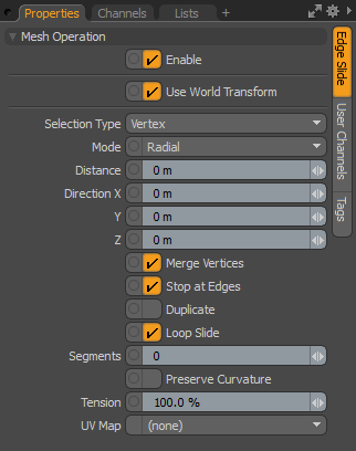
| 8. | On the right panel, open the Edge Slide tab, and set Mode to Linear. |
The tool handles display in the 3D viewport.
| 9. | In the 3D viewport, click-and-drag the green handle upwards. |
The selection set moves upwards.
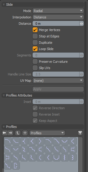
Direct Modeling - Slide Tool Properties
The Direct Modeling Slide tool is found in the toolbox located on the left panel of the interface.
|
Mode |
• Linear - Slides elements along either of two intersecting edges. This is useful when sliding vertices or polygon selections. When enabled, the Direction X/Y/Z triplet is activated. • Radial - When enabled, the Direction fields are disabled. The input values for Slide / Edge Slide and Percentage specifies how far to slide the selected loop between the next and previous loops. For example, use this mode for sliding entire edge loops such as widening or narrowing a selected edge loop around an eye. • Face - This mode only works with vertices. Allows you to slide a vertex on a connected polygon. Note: Face mode is only available for the direct modeling tool. |
|||
|
Direction X/Y/Z |
Sets the directional position for X, Y, and Z. |
|||
|
Allows you to choose between Distance and Percent methods for sliding the geometry. • When Distance is enabled, the Distance option is enabled. • When Percent is enabled, the Percentage option is enabled. |
||||
|
Distance |
When Interpolation is set to Distance, set the numeric value and unit system used to move the geometry. |
|||
|
When Interpolation is set to Percent, set the percentage value to slide the selected geometry. You can set the percentage using its initial position (0%) and the neighboring edge or edge loop position (-100% to 100%). |
||||
|
Merge Vertices |
When enabled, vertices are merged when vertices share the same coordinates. For example, sliding an edge 100% results in that edge being merged into its neighbor. Tip: This can be particularly useful when combined with the Stop at Edges option to avoid over deforming geometry. |
|||
|
When enabled, the Slide tool stops the slide when the selected mesh elements reach the surrounding edges. |
||||
|
Duplicate |
When enabled, creates a new element, rather than sliding to the selected element. Tip: Use this option to create new edges or edge loops and place them along the existing curve. |
|||
|
Loop Slide |
Note: Loop Slide is only available for edge selections. When enabled and sliding on an edge selection, constrains the movement along the existing polygonal bounds. |
|||
|
Segments |
Specifies the number of segments for profiles. If the value is 0 and a profile is selected, the Slide tool automatically decides the best adaptive segments for the profile. Note: Duplicate must be enabled for Profiles to work. To specify a profile, see Profiles Options. |
|||
|
When enabled, the new position is computed along a curve through the edges to maintain the overall curvature or surface continuity. Once enabled, the Tension option becomes available, controlling the tightness of the curvature preservation. |
||||
|
Determines the strength of the curvature preservation. The default value of 100% calculates the curvature, placing the new vertex appropriately. Note: Setting the value to 0% is the same as disabling the Preserve Curvature option. Negative values inset the curvature and higher values further offset the vertex out from the curve's position. |
||||
|
Slip UVs
|
When enabled, existing UV mappings applied to the geometry are not disturbed. UV values are generally fixed to specific vertices, so further edits to the geometry may warp, deform, or otherwise distort the UV values in undesirable ways. When this happens, you may need to adjust the map or redo it altogether. To avoid this, enable Slip UVs so as to not disturb any existing UV mapping applied to the geometry. For more information about UV Mapping, see Working with UV Maps. |
|||
|
||||
|
Handle Line Size |
Specifies the line width of vertex handle. |
|||
|
UV Map |
Select a UV map to use Slide on a UV map. When set to (none), the tool works on 3D geometry. |
|||
|
Apply |
Applies property settings. |
Profile Attributes Options
|
Inset |
This specifies the offset amount of X direction of the profile. |
|
Reverse Direction |
If this option is enabled, the 1D profile is evaluated from top to bottom. |
|
Reverse Inset |
If this option is enabled, Inset is reversed. |
|
Keep Aspect |
Automatically sets Inset value based on the aspect ratio of the profile. |
Profiles Options
Mini Preset browser for viewing various profiles. Works the same as the standard Preset Browser.