Jitter
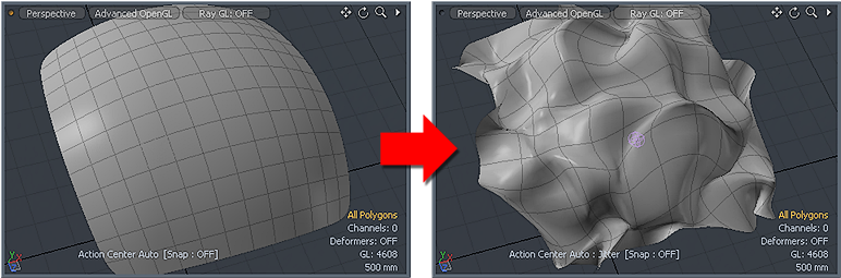
The Jitter tool repositions selected items or components based on a seed number and a range value for the X, Y, and Z axes. It applies a random offset to each vertex or item position for a more random, organic appearance.
Activating the Jitter Tool
Direct Modeling:
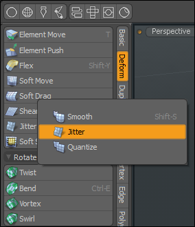
• In the Model layout, on the left panel, open the Deform tab, and click Jitter.
Tip: You can find the tool in the Model layout, in the Deform sub-tab of the modeling toolbox (sometimes as a sub-option of the Smooth or Quantize tools).
Procedural Modeling:
• In the Mesh Ops tab, click Add Operator, and double-click Mesh Operations > Deform > Jitter.
• In the Schematic view, click Add..., and double-click Mesh Operations > Deform > Jitter.
Applying Jitter
| 1. | Activate the Jitter tool. |
| 2. | With the tool active, drag in the viewport to interactively apply the jitter, or type Range values in the tool's Properties panel. |
Changing the Seed value changes the random numbers to produce a variation on the results. This tool uses any active falloffs to target specific areas for the jitter. You can also randomly move, scale, and/or rotate connected selections in X, Y and Z, or U and V direction.
Direct Modeling Example
The following is an example of using the Jitter tool to create a fence with random spacing between each post. This is done by duplicating using the Clone tool. By default the Jitter is applied to the vertices. By enabling the Rigid Translate, Rigid Rotate, and Rigid Scale options, all the duplicates are treated as individual objects. Use these options to quickly create real geometry without having to use Replicators.
Once created, we can use this model to apply a texture image map with random jitter effects, which can be used in a Games Engine. To view a random texture on all duplicates, you can quickly view the results in the 3D viewport without having to render your scene.
To create a fence post:
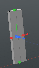
| 1. | Open the Model layout, under the Basic sub-tab in the Toolbox, and click Cube |
| 2. | In the properties on the left panel, set Segment X to 2 and then click-and-drag a shape in the 3D viewport. |
The following properties were used in this example.

Tip: Use the scale transform square handles to make the initial shape.
| 3. | Press the spacebar to drop the tool. |
| 4. | Under the menu bar and above the 3D viewport, click Edges. |
| 5. | Click on the top center edge of the fence post to activate it and press W to activate the Move tool. |
| 6. | Drag the transform handle upwards to make a peaked fence post. |
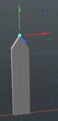
| 7. | Press the Spacebar to drop the tool. |
Create a new UV map:
| 1. | On the right panel, with the Items tab open, navigate to the bottom of the panel and open the Lists tab. |
| 2. | Expand UV Maps, right-click on Texture, and click Clear. |
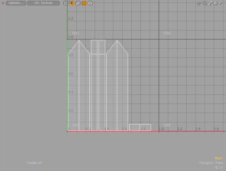
| 3. | Open the UV layout, in the Toolbox on the left panel, click Project. |
| 4. | In the Create UV properties on the Toolbar, set the Projection Type to Atlas. |
The UV layout displays an update UV map, similar to the image below.
To duplicate the fence post:
| 1. | Under the menu bar and above the 3D viewport, click Polygons, and double-click on the fence post mesh. |
| 2. | Open the Model layout, in the Toolbox on the left panel, open the Duplicate sub-tab, and click Clone. |
| 3. | Set the Number of Clones to 10 and click-and-drag in the 3D viewport to position the duplicates. |
| 4. | Press the Spacebar twice to drop the tool. |
To add randomness to the fence:
| 1. | In the Items tab, on the right panel, select the Mesh item. |
| 2. | Under the menu bar and above the 3D viewport, click Edges. |
| 3. | Lasso Select all of the fence posts. |
| 4. | On the Toolbar, open the Deform sub-tab and click Jitter. |
| 5. | Set the Range for the X , Y, and Z values to 29 mm, 10 mm, 10 mm respectively. |
| 6. | Enable Rigid Translate, Rigid Rotate, Rigid Scale, and click Apply. |
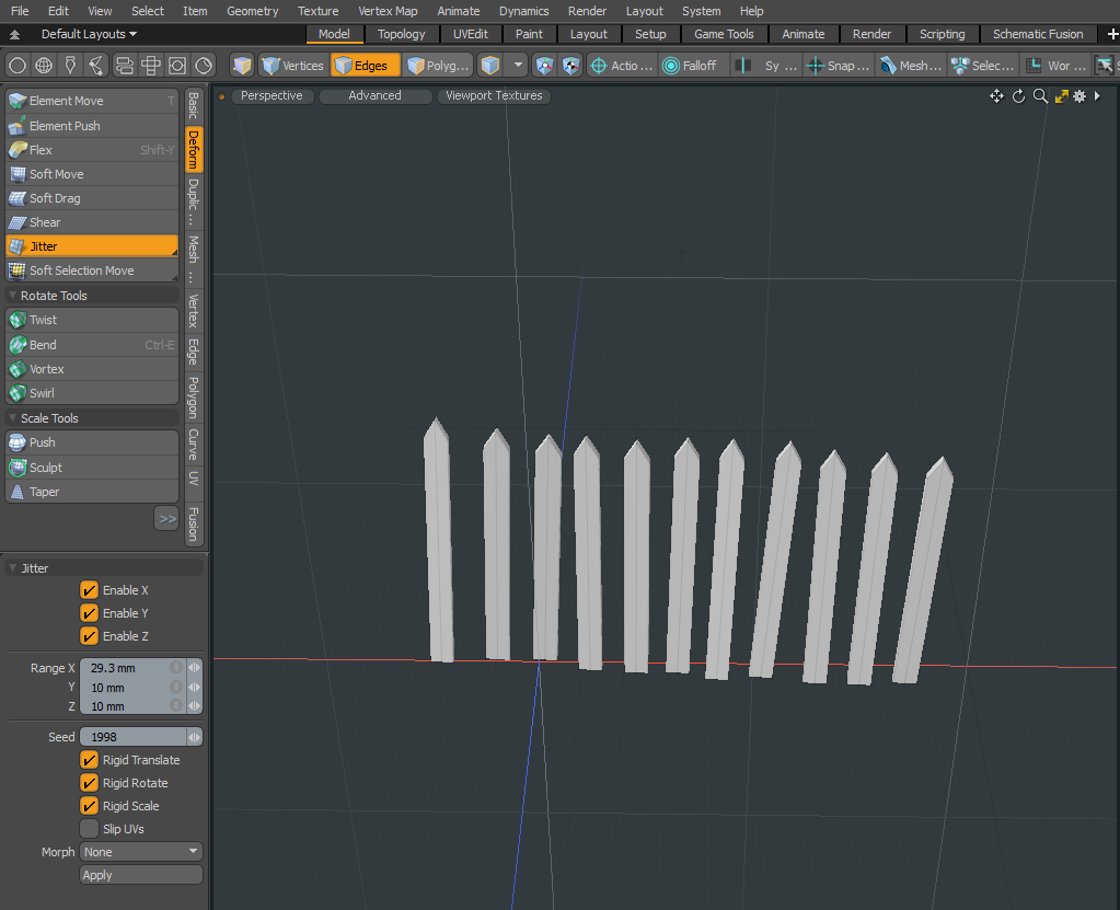
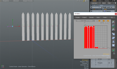
The fence posts are now randomly placed.
| 7. | In the List tab, expand UV Map, right-clickTexture, and select Clear. |
| 8. | On the left panel, open the UV tab, and click Project. |
A new set of UVs is created for all fence posts.
To create a random texture:
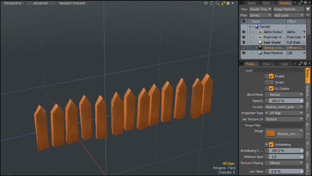
| 1. | On the right panel, open the Shading tab, and select Base Material. |
| 2. | Click Add Layer > Image Map > (load Image), select a texture image, and click Open. |
The fence posts all have the a random texture image map applied.
Procedural Jitter Example
The following is an example of using the procedural Jitter tool to create a fence with random spacing between each post. By enabling the Rigid Translate, Rigid Rotate, and Rigid Scale options, all the duplicates are treated as individual objects. Use these options to quickly create real geometry without having to use Replicators. In addition, a Linear Falloff procedural mesh operation is used to demonstrate how to modulate the Jitter mesh operation.
| 1. | In Model layout, on the left panel in the Basic sub-tab, click the |
| 2. | On the left panel, set the following properties and click Apply. |
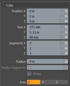
| 3. | Under the layout menus, click Edges, and select the top center edge. |
| 4. | Press W and drag the edge upwards to create a pointed fence post. |
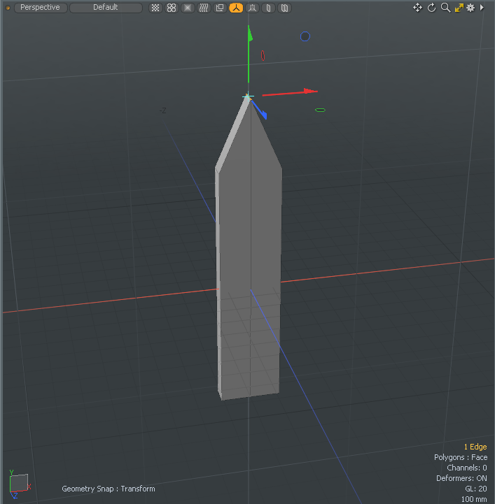
| 5. | Press the Spacebar twice to drop the active tools. |
| 6. | Under the layout menus, click Polygons, and double-click on the fence post. |
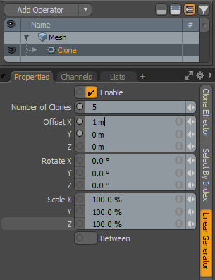
| 7. | On the right panel, open the Mesh Ops tab, and click Add Operator > Mesh Operations > Duplicate > Clone. |
| 8. | On the right panel, open the Linear Generator tab and set Number of Clones to 5, and Offset X to 1m. |
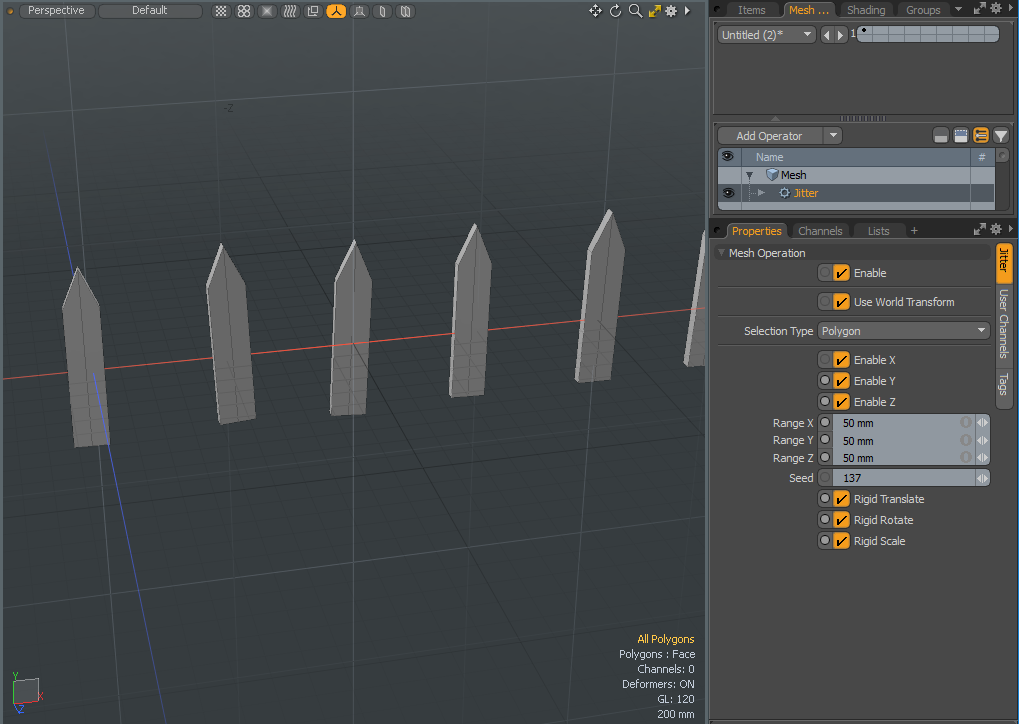
| 9. | On the right panel, select the top mesh item, click Add Operator, and double-click Mesh Operations > Deform > Jitter. |
| 10. | Set the Range X, Y, and Z values to 50 mm and enable Rigid Translate, Rigid Rotate, and Rigid Scale. |
The fence posts are randomly positioned.
| 11. | On the right panel, expand Mesh , Jitter, Tool Pipe, and click (Add Tool Pipe). |
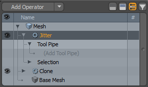
| 12. | At the top of the Mesh Operations dialog, type Linear Falloff, and double-click on its icon to add it to your scene. |
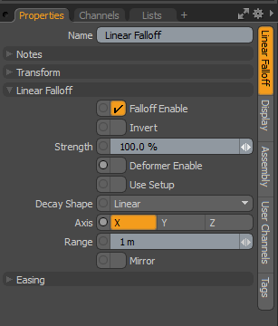
The Linear Falloff uses a straight line to define the falloff.
| 13. | In the properties for the Linear Falloff, on the Linear Falloff tab, set Axis to X. |
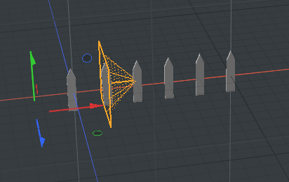
| 14. | Press W and drag the red transfer handle through the series of fence posts. |
The Jitter properties are applied to each fence post as you drag the Linear Falloff over them.
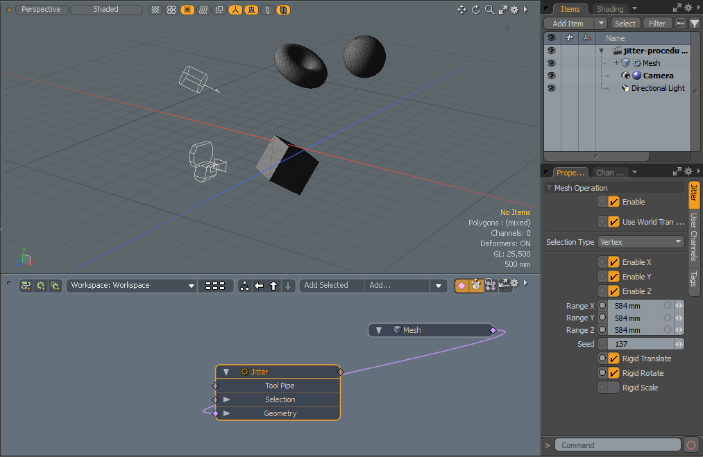
Schematic Jitter Example
In this example, we are using a number of primitives to demonstrate how to apply the Jitter tool using the Schematic viewport.
| 1. | Under the main menu, click Model. |
| 2. | On the left panel, on the Basic tab, click the |
| 3. | Right-click in the 3D viewport to position the cube, and then press the Spacebar twice to drop the tools. |
| 4. | On the left panel, on the Basic tab, click the |
| 5. | In the 3D viewport, click-and-drag on the handles to reposition the mesh item, and press the Spacebar twice to drop the tools. |
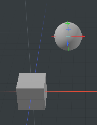
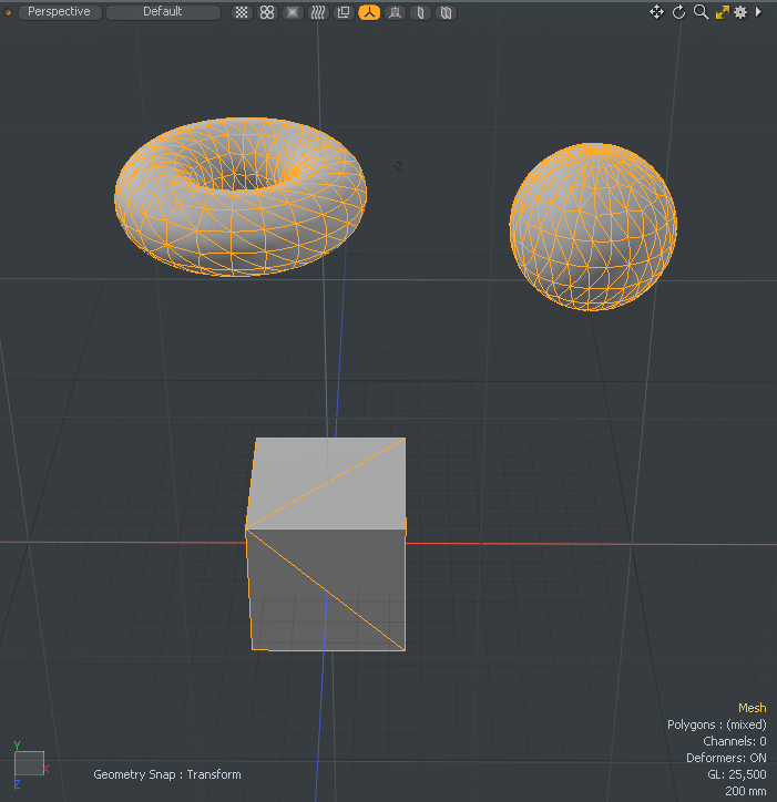
| 6. | Repeat these steps to add a Torus primitive to your scene. |
| 7. | Under the main menu bar, click Setup. |
The Schematic viewport is displayed at the bottom of the layout.
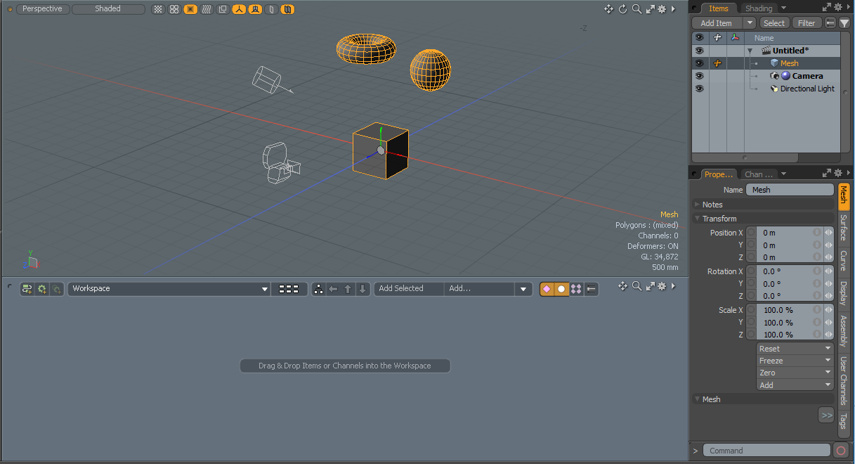
| 8. | On the right panel, open the Items tab, and drag your mesh item onto the Schematic viewport. |
The Mesh node displays in the Schematic viewport.
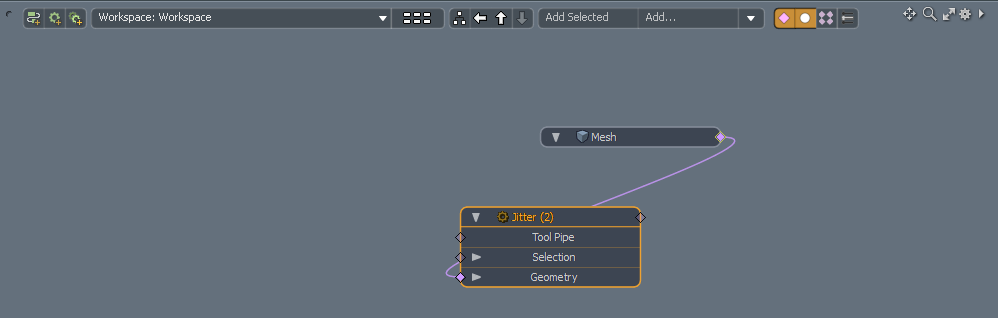
| 9. | In the Schematic viewport, click Add..., and double-click Mesh Operations > Deform > Jitter. |
The Mesh node is automatically connected to the Jitter node.
| 10. | On the right panel, change the Range X, Y, and Z values, and enable Rigid Translate, Rigid Rotate, and Rigid Scale. |
The mesh items are randomly positioned and scaled.
Jitter Tool Properties
|
Enable |
Toggles the tool off and on. This option is only available for a procedural modeling mesh operation. |
||||
|
Use World Transform |
When enabled, the mesh operation maintains the world space on the input layer. This option is only available for a procedural modeling mesh operation. |
||||
|
Selection Type |
Allows you to specify the selection type to apply Jitter to. • Vertex - Jitters the selected vertices and leaves the unselected vertices in your scene. • Edge - Jitters the selected edges and leaves the unselected edges in your scene. • Polygon - Jitters the selected polygon and leaves the unselected polygons in your scene. |
||||
|
Enable X/Enable Y/Enable Z |
Enables the random jittering movement on a per axis basis for each axial direction. |
||||
| Enable U / Enable V |
When using the UV Editor, these options are displayed on the left panel. They enable the random jittering position on the U and V directions. Note: Range Z is not available in the UV Editor. |
||||
|
Range X/Y/Z |
Controls the maximum random offset distance. Changing this value adjusts the strength of the jittering effect. |
||||
|
Seed |
Provides the initial number for Modo to use when generating the random values. Each seed produces different random results. |
||||
|
Rigid Translate |
Randomly move connected selections in X, Y and Z, or U and V direction. If you have a UV map, this option allows you to move each stacked island. Note: If using the direct modeling Jitter tool, the UI element displayed is Translate. If using the procedural mesh operation Jitter, the UI element displayed is Rigid Translate. |
||||
|
Rigid Rotate |
Randomly rotate connected selections in X, Y and Z, or U and V direction. Note: If using the direct modeling Jitter tool, the UI element displayed is Rotate. If using the procedural mesh operation Jitter, the UI element displayed is Rigid Rotate. |
||||
|
Rigid Scale |
Randomly scale connected selections in X, and Z, or U and V direction.
Note: If using the direct modeling Jitter tool, the UI element displayed is Scale. If using the procedural mesh operation Jitter, the UI element displayed is Rigid Scale. |
||||
| Locked Stacked |
When using the UV Editor, this option displays. It locks and unlocks stacked UV's so they can be randomized as a group or as individual UV islands.
|
||||
|
Slip UVs |
When enabled, edits applied to the geometry do not change the existing UV map. UV values are generally fixed to specific vertices; therefore, further edits to the geometry may warp, deform, or otherwise distort the UV values in undesirable ways. When this happens, you may need to adjust the map or to redo it altogether. To avoid this undesirable result, you enable Slip UVs so as to not disturb any existing UV mapping applied to the geometry.
|
||||
|
Morph |
Determines how Modo treats stored morphing information when applying transforms (such as the Move, Rotate, or Scale transforms) to geometry. There are three options for controlling how Modo deals with the morph map vertex data when applying any transforms.
• None - Transforms selected (visible) morphs independent of their source, but does not affect unselected morph data.
• Transform - Transforms morph data along with the base mesh.
• Keep Positions - Converts morph data into an absolute morph map. All vertices retain their pre-transformed positions. Note: In previous versions of Modo, to transform a morph along with its base, you needed to select it in the Vertex Map list. If you didn't, when Modo recalled the relative morph map data, it would produce distorted, undesirable results; therefore, it was easy to accidentally spoil a model. To remedy this problem, current versions of Modo have three options to deal with the morph map vertex data. |