UV Transform
This is a procedural tool for transforming a source mesh's vertices to the world position of the surface of a target mesh, using a UV map on the target mesh. Essentially, this places the source mesh geometry on the surface of a target mesh, using the target UV map as a guide to locate vertex positions. By using this tool, you can quickly wrap a mesh over the surface of another mesh.
|
|
|
The tool operates in a similar way to UV mapping, but in this case the mapping region is located in 3D space, as is the source geometry. The tool also lets you use a UV map from the source mesh as a source of geometry, instead of geometry from the 3D space. This is done using the Source UV Map setting.
UV Transform Mapping Region
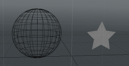
Modo uses a flat, square region in 3D space to determine the area from which to transform the source geometry. This area can be repositioned and resized as required, but is always aligned to one of the dominant planes (XY, XZ, YZ) using the Axis setting. You must ensure that the source geometry is placed over the region for the transform to take effect.
For example, if you want the mapping region to be on the XY plane (as shown above), set Axis to Z. Any target geometry that falls within the X, Y bounds of the mapping region will be transformed.
Translating the source geometry across the mapping region will move the transformed mesh over the surface of the target mesh, as it is effectively sliding over the surface of the target UV map.
Wrap to Surface
By default, the source geometry is flattened onto the surface of the target mesh. However, by unchecking Wrap to Surface, you can preserve the depth of the source mesh when it is applied to the target mesh. This lets you wrap a 3D object around the surface of another mesh, as shown below.
![]()
Also, if Wrap to Surface is unchecked, the distance of the source mesh from the transform region plane creates a corresponding displacement of the transformed mesh from the target mesh surface. For example, if Axis is set to Z, the Z position of the source mesh determines the displacement distance.
The image below shows a transformed mesh displaced from the target mesh by increasing the Position Z of the source mesh. Observe also how the transformed mesh size increases as the distance increases.
![]()
Note: The displacement from the surface does not occur when Wrap to Surface is unchecked. However, you can add a displacement to a flat transform mesh using the Push setting.
Using UV Transform
The steps below describe a typical use of the UV Transform tool using the Mesh Operations, starting with an empty scene. The example uses procedural meshes but this is not compulsory. If you already have two mesh layers containing a source mesh and a target mesh, where the target mesh has a UV map, you can skip to step 8.
Note: You can also right-click on the mesh in the 3D viewport and select Item Operations > Add Mesh Operation.
| 1. | Add a source mesh to the scene. This will be transformed onto the target mesh. In this example, let's add a Star on the XY plane. In the Mesh Ops tab, click Add Operator and double-click Mesh Operations > Create > Curves > Star. |
![]()
| 2. | Let's name this mesh. In the Mesh Ops tab, click on the item Mesh and type Star Source Mesh in the Properties tab Name field. |
| 3. | Let's fill the star to make it solid. First select the star in your scene. Then click Add Operator and select Mesh Operations > Curves > Curve Fill. |
| 4. | Add a new mesh layer to the scene for the target mesh. To do this procedurally, click Add Item and select Mesh. |
| 5. | Let's name this mesh. In the Properties tab Name field below type the name Target Sphere. |
| 6. | Add a target mesh to the new layer. Let's add a procedural sphere. Click Add Operator and select Mesh Operations > Create > Primitives > Sphere. |
![]()
| 7. | Ensure the target mesh has a UV map (one should be created by default). Open the Lists tab and check the UV Maps list. |
![]()
| 8. | Move the target mesh away from the origin so that you can see both meshes. You'll need to be in Items mode to move a procedural mesh (use the W key to open the move tool). |
| 9. | Select the Star Source Mesh item. |
| 10. | Add the UV Transform tool: Open the Mesh Ops tab, click Add Operator and select Mesh Operations > Deform > UV Transform. |
This opens the Create UV Transform dialog.
![]()
| 11. | Set the Target Mesh to Target Sphere. |
| 12. | Set Target UV Map to Texture and click OK. |
The tool is added to the Mesh Ops list.
![]()
You'll see the square transform region in the 3D viewport.
![]()
Note: If the star overlaps the UV transform region (as shown above), only the part of the source mesh within the region is transformed. Consequently, the mesh is stretched between the original and transform locations.
| 13. | Select the UV Transform, in the Properties tab, ensure the Axis is set to Z. In this case, this aligns the mapping region to the source mesh. |
| 14. | You can now transform the source mesh (the star) and/or the mapping region, so that the source mesh is enclosed by the mapping region. |
a) In the Items list, select the UV Transform mesh operator, open the Properties tab on the lower right panel, and click the Use Source Transform checkbox.
b) In the upper left corner of the viewport, change the View Type to Front.
![]()
c) In the Items tab, select Star Source Mesh, press W, and use the handles to reposition the item.
d) Press R to rescale the Star Source Mesh and use the handles to rescale the item.
![]()
Alternatively, disable the Use Source Transform option, adjust the Offset (mm) and Scale (%) properties respectively . For example, set Offset U and V to 0 and Scale to 120%.
![]()
You can now see the source geometry transformed onto the surface of the target mesh. To see this more clearly, hide the target mesh to show only the transformed mesh.
Note: If you move the target mesh, the transformed mesh follows.
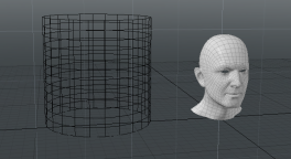
Using a Source UV Map
The tool provides two options for source geometry, you can either use a source mesh or a source UV map. To use a UV map, set the Source UV Map parameter in the tool properties. The image below shows a source mesh, and the result of transforming its UV map on to a cylinder.
|
|
UV Transform Properties
Edit the following parameters to customize the UV Transform tool. They are found in the Properties viewport on the UV Transform tab.
|
UV Transform |
|
|
Enable |
Toggles the tool on and off. |
|
Target Mesh |
The source mesh is transformed to this mesh. |
|
Target UV Map |
Sets the UV map to use for the source transform. This is required to work out how to transform from the target to the source. |
|
Source UV Map |
Select a UV map to locate the vertices in the source mesh. By default this isn't set, and Modo uses the vertex position in the axis given by the Axis value to calculate the position to look up on the target UV map. |
|
Use Source Transform |
|
|
Axis |
Determines the axis that is used to calculate the target UV position. Choose one of the following: • X - Use YZ values. • Y - Use XZ values. • Z - Use XY values. Note: Axis is not used if Source UV Map is set. |
|
Offset U/V |
Sets the position of the center of the mapping region, relative to the origin. |
|
Scale |
Sets the scale of the mapping region. At 100% the region is 1m x 1m. |
|
Wrap to Surface |
Check this to transform the mesh, preserving the depth of the source geometry. By default, this is off and the source geometry is flattened. |
|
Push |
The distance to offset the transformed source geometry from the surface of the target mesh. |
UV Transform Procedural
The UV transform has the following procedural sub-tools:
• Selection - Allows you to limit the transform to a selection of elements.
• Target - The target mesh.
• Geometry - This lists any geometry that is affected by the tool. Meshes are connected automatically if they are below the tool in the Mesh Operations list. You can connect additional meshes by clicking (Add Geometry) to open the Preset Browser. From there you can select an existing mesh or add a new, empty mesh.
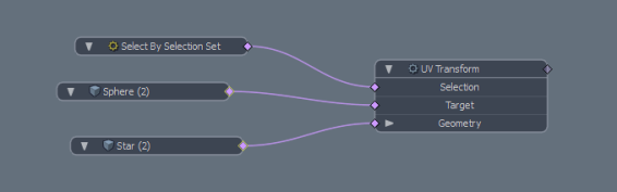
UV Transform Schematic
The UV Transform node has the same inputs as the procedural version.