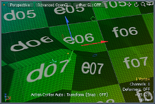
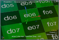
Axis Rotate
The Axis Rotate tool allows you to rotate a selection by a specific number of degrees. The Axis Rotate tool is different from the standard Rotate tool in that it is limited to editing a single axis at a time, determined by the Work Plane position, when activated. It also has a different on-screen control display than the other transform tools, providing a greater degree of control over the amount of rotation depending on how long or short you drag out the handle length (only when the Advanced Handle option is enabled). Holding the Ctrl key constrains the rotation to fixed intervals defined by the Snap Angle amount. After applying a transform amount, you may press the middle mouse button to re-apply the previous offset amount, making it easy to apply an edit multiple times. The command can be activated in the Basic sub-tab of the Modeling viewports. You may need to press the Shift key to show alternate tools in the toolbox. You can also activate the tool from the menu bar under Edit >Transform > Axis Rotate or by pressing the Alt+Shift+E keyboard shortcut.
In the component modes (Vertices, Edges, and Polygons), the tool affects the selected geometry directly. When nothing is selected, it affects all active foreground geometry. Active foreground items are those that are visible and selected (highlighted) in the Items (Scenes) List. In Items mode the tool affects all the currently-selected items in the Item List, if nothing is selected, then the tools appear to do nothing. In material mode, it works the same way as in any of the component modes. Lastly, in the Center and Pivot modes, it modifies the Center or Pivots respectively.
Note: You need to physically select either the Center or the Pivot itself (depending on the mode) prior to activating the tool. As in Items mode, with no selection, the tool appears to do nothing.
When you define any of the various falloffs Modo provides, application of the tool can be attenuated across a user-defined area. For more on using falloffs, please refer to the Using Falloffs topic.
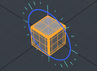
Once the tool becomes active, Modo draws the relevant tool handle within the viewport. At this point, you can simply click and haul anywhere inside the desired viewport to interactively rotate the geometry. Depending on the action center, this may also set the rotation center, based on the mouse click position intersecting the Work Plane.
Additionally, you may prefer to utilize the on-screen display, either clicking on the wheel to rotate to a specific amount, or by dragging the handles on the value bar across the top of the viewport (when Advanced Handles is enabled). When clicking on the wheel, a handle is drawn, displaying the number of degrees. When using this handle the rotation sensitivity is adjusted based on the distance the mouse is from the handles as you drag. This can be thought of as extending a lever. The longer the lever, the more mouse movement is required to rotate the element and, thus, the granularity of control is increased. To interactively scale the size of the handles themselves, you may use the - (minus) and = (equals) keys on the keyboard to adjust them: minus makes them smaller, while equals makes them larger.
The Axis Rotate tool also respects the settings for the Action Center, and originates the action from the defined position. For more information on understanding and using Action Centers, please refer to the Specifying Action Centers and Falloffs topic.
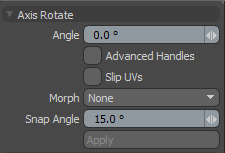
The following Axis Rotate options are available when in component mode:
|
Angle |
Use the Angle input field to apply specific rotational value, calculated in degrees. When adjusting an object interactively in the viewport, the Angle input field displays the current rotation amount, providing useful feedback. |
||||
|
Advanced Handles |
Determines whether or not the rotation display widget displays the additional controls and information in the viewport. When Advanced Handles are enabled, the handle itself can be snapped to the angle indicators in the display. Press and hold the X key to temporarily toggle snapping. |
||||
|
Slip UVs |
Only in component selection modes. UV values are generally fixed to specific vertices; subsequently, further edits to the geometry may warp, deform, or otherwise distort the UV values in undesirable ways, requiring you to adjust the map or redo it altogether. To avoid this undesirable result, you can enable the Slip UVs function, so as to not disturb any existing UV mapping applied to the geometry.
|
||||
|
Morph |
Only available in component modes. Determines how Modo treats stored Morph information, when applying transforms to geometry (Move, Rotate, Scale). In previous versions of Modo, in order to transform a morph, along with its base, it needed to be selected in the Vertex Map list. If it wasn't, relative morph map data, when recalled, would produce distorted, undesirable results. If you are unaware of the requirements, it's easy to accidentally mess up a model. To remedy this problem, there are now three options controlling how the morph map vertex data is dealt with when applying any transforms: • None - Unselected Morph data is not affected, though selected (visible) morphs can still be transformed, independent of their source. • Transform - With this option selected, Morph data is transformed, along with the base mesh. • Keep Positions - With this option selected, Morph data is converted into an absolute morph map and all vertices retain their pre-transformed positions. |
||||
|
Snap Angle |
Defines the angle quantization amount when holding down the Ctrl key. Make sure to press Ctrl prior to clicking in the 3D viewport. |
The following additional Axis Rotate options are available when in Items mode:
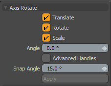
|
Translate |
Move all of the currently-selected items in a single axis dimension. |
|
Rotate |
Rotate all of the currently-selected items in a single axis dimension. |
| Scale | Scale all of the currently-selected items larger or smaller in a single axis dimension. |
For information about the other options available in Items selection mode, see the table above.
The Snapping and Geometry Snap options are also displayed when the Axis Rotate tool is activated. For more information, see Applying Snapping.
