Edge Chamfer
Edge Chamfer allows you to round the edges of a mesh, similarly to Edge Bevel. You can customize the effect by fine-tuning the tool's properties, use Profile shapes to determine the shape of the chamfer, and modulate the effect using Falloffs.
Edge Chamfer has a few advantages over the Edge Bevel tool:
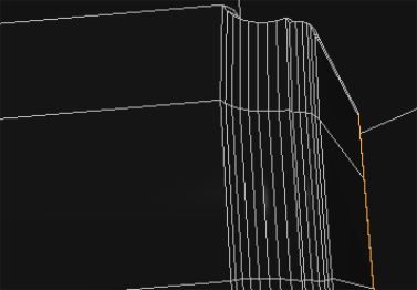
• Edges are offset from the source in parallel, producing better geometry. You can toggle this behavior with the Offset in Parallel option in the Edge Chamfer Properties.
|
|
|
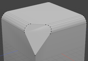
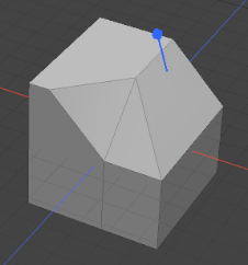
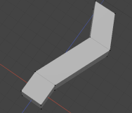
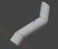
Edge Bevel |
Edge Chamfer |
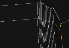
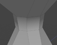
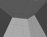
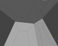
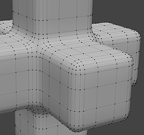
• Cleaner corner geometry compared to Edge bevel.
|
|
|
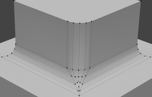
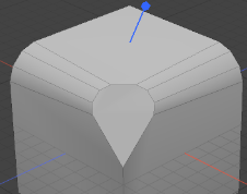
Edge Bevel |
Edge Chamfer |
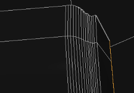
• Produces cleaner UVs by handling discontiguous edges better.
|
|
|
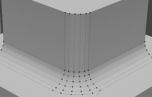
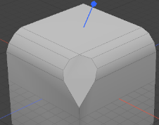
Edge Bevel |
Edge Chamfer |
Using Edge Chamfer
Direct Modeling
It's best to use the Modo or Model layouts when working with Edge Chamfer. This workflow example uses the Modo layout.
| 1. | In Edges selection mode, select the edges to round. |
| 2. | Open the Model toolbar on the left panel and click the Edge sub-tab. |
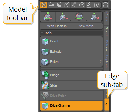
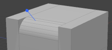
| 3. | Click Edge Chamfer, then click in the viewport to activate the tool. |
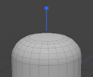
A blue tool handle appears in the 3D viewport, indicating that the tool is active.
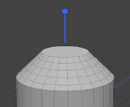
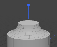
| 4. | Drag on the handle to adjust the inset, or click the Tool Properties button on the left panel to adjust the tool's settings. |
For more information on the tool properties, see Edge Chamfer Properties.
You can use Falloffs to modulate the strength of the tool on different parts of the geometry. For more information on working with Falloffs, see Using Falloffs.
Procedural Edge Chamfer
The Edge Chamfer mesh operation allows you to round edges on a mesh procedurally.
| 1. | In Edges selection mode, select the edges to chamfer. |
| 2. | On the right panel, click the Mesh Ops tab. |
Note: If you're working in a layout where the Mesh Ops tab is not visible by default, click the + button on the right of the tab names, and select Data Lists > Mesh Ops.
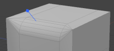
| 3. | Click the Add Operator button, and under Mesh Operations, click Edge , then double-click Edge Chamfer. |
A blue tool handle appears in the 3D viewport, indicating that the tool is active.
You can expand the Edge Chamfer mesh operation in the list by clicking the arrow ![]() in front of it. This reveals the inputs the operation uses:
in front of it. This reveals the inputs the operation uses:
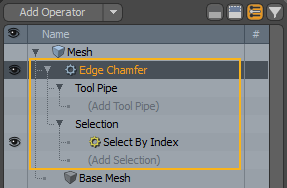
• Tool Pipe - Add falloffs and sub-tools to the operation.
• Selection - Select edges or modify your existing selection. For more information on procedural selection, see Procedural Selection.
| 4. | Drag on the handle to adjust the inset, or open the Properties tab and adjust the tool's settings. To do this, select the Edge Chamfer mesh operation in the list. This opens the Properties tab on the right panel. |
For more information on the mesh operation's properties, see Edge Chamfer Properties.
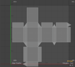
Edge Chamfer in the Schematic
You can also use Edge Chamfer when working in the Schematic viewport.
Note: For more information on working with Schematic viewport in general, see Schematic Viewport.
To open the Schematic viewport:
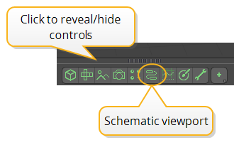
• In the Modo layout, click the thin gray line below the 3D viewport, and click the Schematic viewport ![]() button.
button.
>
MadCap:conditions="Default.NoTranslate">OR
• Switch to the Setup layout from the menu bar by clicking Layout > Layouts > Setup.
To use the Edge Chamfer node:
| 1. | Click Add..., and under Mesh Operations > Edge, double-click Edge Chamfer. |
This adds the Edge Chamfer node to the viewport and opens its properties on the lower right panel. You can also see a blue tool handle appear in the 3D viewport, indicating that the tool is active.
Tip: Selecting the edges in the viewport in advance adds the Select By Index selection operator containing your selection. You can edit the selection through the node by selecting it. This opens its properties in the lower right panel. For more information see Select by Index.
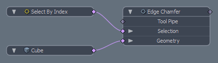
The node has the following inputs:
• Tool Pipe - Add falloffs and sub-tools to the operation.
• Selection - Select polygons or modify your existing selection.
• Geometry - Any geometry that is affected by the tool.
| 2. | Drag the blue tool handle in the viewport or adjust the properties in the Properties tab to get the result you need. |
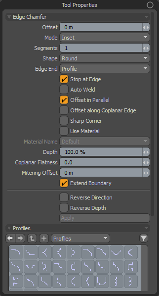
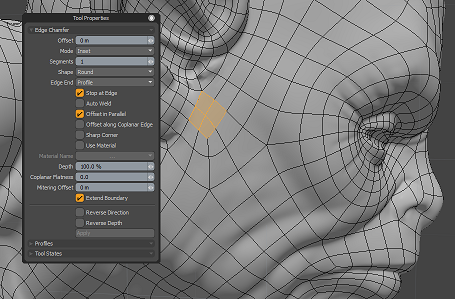
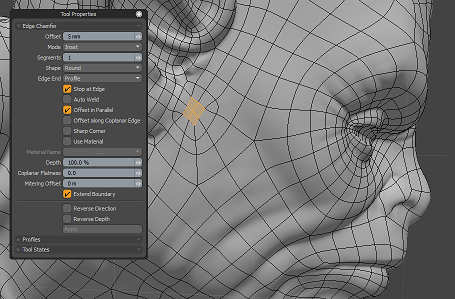
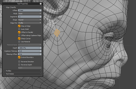
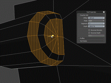
Edge Chamfer Properties
Edge Chamfer has the following properties.
|
Offset |
Specifies the chamfer inset or width, depending on what Mode option is used. |
||||||||
|
Mode |
There are two ways you can use the tool: • Inset - Determines the distance away form the original edge. The inset is parallel to the source edge. • Width - Determines the actual width of the new chamfer. |
||||||||
|
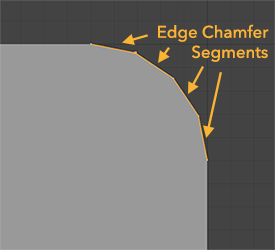
Segments |
The number of divisions for rounding the edge. This is similar to the Edge Bevel tool's Level property, but allows you to set an odd number of segments. The more segments you have, the smoother the chamfer. |
||||||||
|
Shape |
Specifies the chamfer shape. The options are:
|
||||||||
|
Edge End |
Specifies the shape created at the end of the selected edges. The following options are available.
|
||||||||
|
Stop at Edge |
When enabled, it prevents the geometry from overrunning when using a large offset size. |
||||||||
|
Auto Weld |
When enabled, the new inset vertices on the same position are merged into one.
|
||||||||
|
Offset in Parallel |
Edge Chamfer offsets edges from source position in parallel. When Offset in Parallel is disabled, new vertices are placed along the edge at the specific offset distance from the source vertex, similar to the Edge Bevel tool.
|
||||||||
|
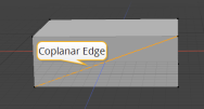
Offset along Coplanar Edge |
Coplanar edges are edges that connect two polygons on the same plane.
Usually, coplanar edges are unnecessary edges in beveling. Edge Chamfer hides coplanar edges before chamfering and computes the inset vector from incoming and outgoing edges at the vertex on the face. However, sometimes you need to inset vertex positions along coplanar edges. Offset along Coplanar Edge allows you to offset vertex positions along connecting coplanar edges.
|
||||||||
|
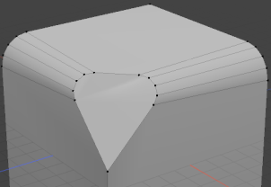
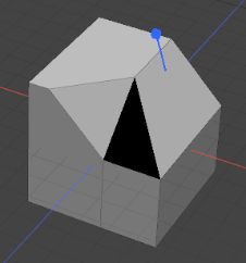
When enabled, keeps chamfered corners as sharp as possible. For edges shared by three or more polygons, the polygons are grouped into pairs and new faces are created between each pair, ignoring polygons not part of a pair. At junctions between three or more edges, extra polygons are inserted to bridge any gaps created by the extrusion. Extra polygons are also inserted at the bare ends of edges to keep the shape closed and planar as the edge is chamfered.
Sharp Corners enabled, keeping the corners of the chamfer sharp and removing unnecessary triangles. |
|||||||||
|
Use Material |
When enabled, you can choose an existing material to apply to all newly created geometry. When disabled, the tool uses the neighboring material. |
||||||||
|
Material Name |
When Use Material is enabled, you can select the material to be used from this dropdown. |
||||||||
|
Depth |
Adjusts the roundness of chamfered edges. 100% is the default value for round bevel. 0% makes round positions flat and -100% produces a negative radius.
|
||||||||
|
Coplanar Flatness |
Edge Chamfer hides all coplanar edges before modifying the edge, to remove unnecessary complexity. This is the threshold value to detect coplanar edges. |
||||||||
|
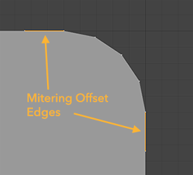
The Mitering Offset option creates extra co-planar polygons beside the outer chamfered edges. Increasing the value increases the distance between the outer chamfered edge and the edge of the added polygon.
This option is useful to smooth artifacts on connecting polygons, allowing for a better transition between a chamfered edge and its connecting polygon.
Offset = 150mm
|
|||||||||
|
When enabled, the boundary of selected edges can be extended outward. This option is available both for procedural and direct Edge Chamfer.
|
|||||||||
|
Reverse Direction |
When enabled, the start and end of the profile curve is reversed. |
||||||||
|
Reverse Depth |
When enabled, the depth direction of the profile shape is reversed. You can use Depth to control the depth amount. |
||||||||
| Profiles |
Select a 1D profile shape to use on the chamfered edge. |

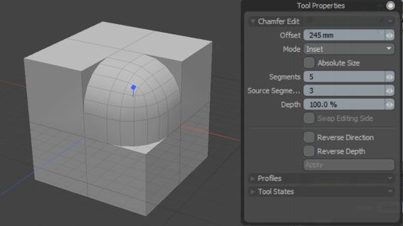
Chamfer Edit
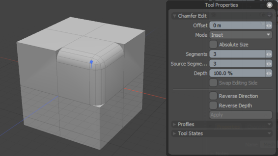
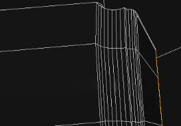
Chamfer Edit allows you to refine your chamfered and beveled faces after a Bevel or Chamfer operation has been applied. The tool increases the number of segments on chamfered faces and also changes the width of faces on chamfered edges.
Adding more segments to an existing chamfered edge with the Chamfer Edit tool.
You can also assign profiles to chamfered edges using the Chamfer Edit tool, which apply a curve of your choice to an edge to create interesting forms for your edges.
Note: The Chamfer Edit tool does not currently support editing rounded beveled faces.
Using Chamfer Edit
The Chamfer Edit tool is available in both direct modeling and procedural modeling workflows. To understand the difference between these workflows, see Modeling Techniques.
Direct Modeling
The direct modeling Chamfer Edit tool can be found in the Polygon tab on the Model layout. To apply a chamfer edit to an existing chamfered or beveled edge using direct modeling tools:
- Click Polygons to activate Polygon Selection mode.
- Select the two outer polygons of a beveled or chamfered edge.
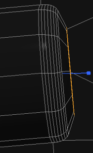
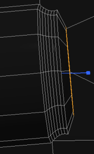
- Click Chamfer Edit in the Polygon tab to activate the tool, and drag the blue widget in the viewport to change the offset of the chamfer.
- Click Tool Properties or press K to open the Tool Properties popover, and change Segments to 5.
The selected faces have five new segments added to them, causing the corners to become rounder.
Note: See Chamfer Edit Tool Properties to learn more about the different properties available on the Chamfer Edit tool.
Procedural Modeling
Procedural mesh operations can be found on the Model layout in the Mesh Ops tab. To apply a chamfer edit to an existing chamfered or bevel edge using procedural mesh operations:
- Click Polygons to activate Polygon Selection mode.
- Select the two outer polygons of a beveled or chamfered edge.
- Click the Mesh Ops tab in the Model layout.
- Click Add Operator and type Chamfer Edit into the search field.
- Double-click Chamfer Edit to add it to the mesh operations stack.
- Drag Offset in the Chamfer Edit properties to adjust the inset of the chamfer.
- Change Segments to 5 to add more segments to each selected face.
Tip: To use profiles with the procedural chamfer edit mesh operation, add a Content Preset to the Tool Pipe menu under the Chamfer Edit in the Mesh Ops tab.
Chamfer Edit Tool Properties
With the Chamfer Edit tool selected, click Tool Properties or press K to open the Tool Properties panel.
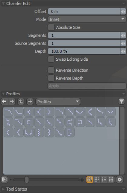
The Chamfer Edit Tool Properties.
|
Enable |
Enables or disables the chamfer edit operation on the mesh. Note: The Enable option is only available in the Chamfer Edit mesh operation. |
||||
|
Offset |
Specifies the chamfer inset or width, depending on what Mode option is used. |
||||
|
Mode |
There are two ways you can use the tool: • Inset - Determines the distance away from the original edge. The inset is parallel to the source edge. • Width - Determines the width of the new chamfer. |
||||
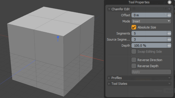
| Absolute Size |
Enabling Absolute Size allows you to edit the offset of a chamfered edge assuming that a zero offset is a straight edge and any positive number above zero will be a curved edge. When Absolute Size is not enabled, an offset value of zero represents how curved the edge was before Edit Chamfer was activated.
Offset 0 with Absolute Size
Offset 0 without Absolute Size |
||||
|
Segments |
The number of divisions for rounding the edge. The more segments you have, the smoother the chamfer.
|
||||
|
Source Segments |
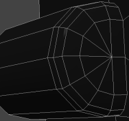
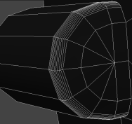
Source Segments allows you to edit the number of segments and offset of a chamfered edge. This tool is useful when making edits to larger models that already have rounded edges. In order for the tool to work, the Source Segments parameter must match the amount of segments selected.
Using the Chamfer Edit tool to increase the Offset and Segment amounts of a chamfered edge. |
||||
|
Depth |
Adjusts the roundness of chamfered edges. 100% is the default value for round bevel. 0% makes round positions flat and -100% produces a negative radius.
|
||||
|
Reverse Direction |
When enabled, the start and end of the profile curve is reversed.
|
||||
|
Reverse Depth |
When enabled, the depth direction of the profile shape is reversed. You can use Depth to control the depth amount.
|
||||
|
Profiles |
Select a 1D profile shape to use on the chamfered edge.
A chamfered edge with a profile assigned. Note: The Profiles option is only available on the direct modeling Chamfer Edit tool. |