Exploring the Layout
When you first open Modo after installing it, this is the interface you're presented with. It was designed and refined over multiple versions for the smoothest user experience. Users of any previous version of Modo are very familiar with this tabbed version of the interface, where each focused workspace is selected directly using the tabs across the viewport.
Each of the workspaces are set up as three main sections. The left-side column is for tools and commands, the center viewport is the most frequently used in Modo, and lastly, the right-hand side houses information regarding the scene: its many items and their respective attributes. Understanding all the various areas and their roles in working in Modo is essential to getting the most out of it.
The image below highlights the main interface sections. See the corresponding numbers below for details.
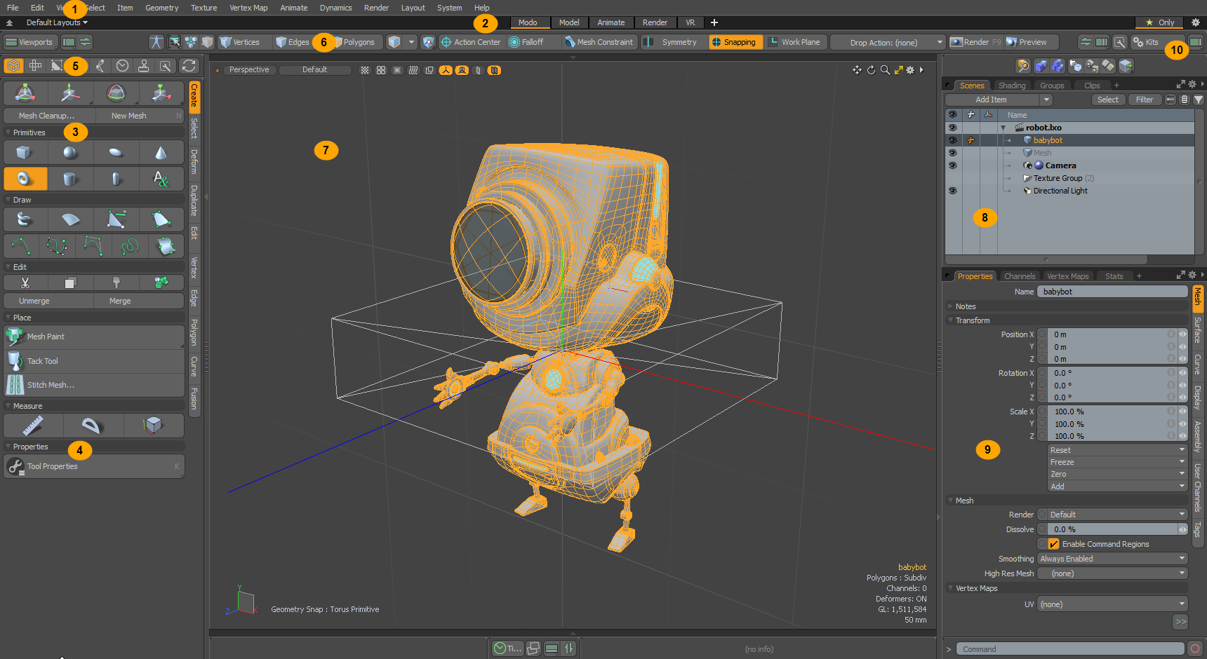
1 — Application Menu Bar

Any function in Modo is available from the menu bar, organized by their respective application. Click any of the menu bar items to reveal a list of commands. Most commands in the menu bar can also be found elsewhere in the application as buttons, or are available through keyboard shortcuts, listed to the right of the menu item (for a list of Modo keyboard shortcuts, see Keyboard Shortcuts). This functional duplication enhances overall workflow.
2 — Switcher Bar

Directly below the menu bar is the switcher bar. Each tab in the switcher bar represents a focused layout, optimized for their specific task. Click on a tab to open the layout. To minimize the switcher bar, click the two upward-facing arrows (![]() ) on the far left, temporarily hiding it. To reopen it, click the remaining thin line.
) on the far left, temporarily hiding it. To reopen it, click the remaining thin line.
You can add your own layouts using the plus button (![]() ) located to the right of the last tab. When you create a new layout, an additional tab is added to the rightmost position of the bar.
) located to the right of the last tab. When you create a new layout, an additional tab is added to the rightmost position of the bar.
You can reorder tabs by clicking and holding a tab and dragging it to a new location. The drop position is indicated by a small orange line.
By the default, you can see the Modo, Model, Animate, Render, and VR layouts. To reveal additional layouts, click the Starred Only ![]() button on the right. You can also click the star button in front of a layout name to highlight specific, often used tabs.
button on the right. You can also click the star button in front of a layout name to highlight specific, often used tabs.

To hide unstarred tabs, click the Starred Only ![]() button again.
button again.
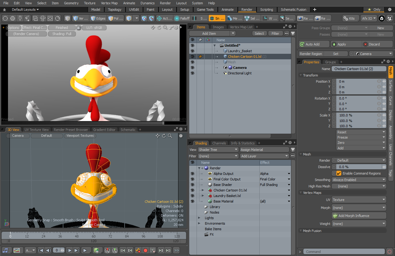
Courtesy William Vaughan
You can reset a layout to its default state by double-clicking its tab. A dialog opens where you need to confirm that you want to reset the layout.
3 — Toolbox
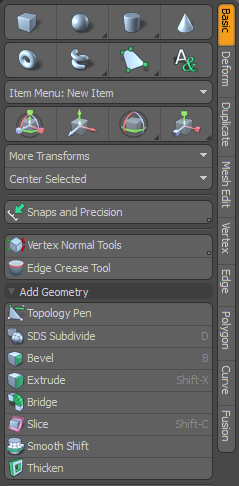
The Toolbox is in the upper area of the left side panel. Nearly every layout has its own dedicated toolbox, illustrated here with the Model layout's Model Toolbox. The Toolbox itself houses the various tools and commands. On the right side of the Toolbox, there are a series of rotated tabs or sub-tabs that organize the various tools by their function. Click on any of them to open the related tools.
To activate a tool, click its button. The active tool is highlighted in orange. You can then manipulate the active tool in the 3D viewport. You can modify some tools using the Ctrl/Cmd, Alt, and Shift keys, and certain tools support additional functions for the middle and right mouse buttons. Depending on the tool's function, its properties appear in the section directly below, where you can modify and apply settings. You can drop (deactivate) a tool by pressing the Space key, or by selecting another tool. Buttons to quickly access alternate toolboxes are available just above the Toolbox.
Recently used tools are also available in the Tool HUD. You can display the HUD by pressing Ctrl/Cmd+Tab. For more details, see Tool HUD.
4 — Tool Properties
Depending on whether you are using Direct Modeling tools, Procedural Modeling , or Schematic Modeling tools, properties are displayed in different areas of the interface.
Direct modeling
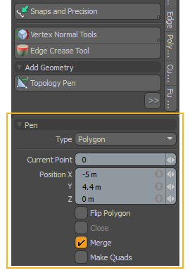
For direct modeling tools, the properties dedicated to the currently-active tool are displayed on the left panel, directly below the Toolbox.
Note: In the Modo layout, a Tool Properties button is displayed. Click it to reveal the properties.
Procedural and Schematic Modeling
For Procedural and Schematic modeling tools, the properties dedicated to the currently-active tool are displayed on the right panel.
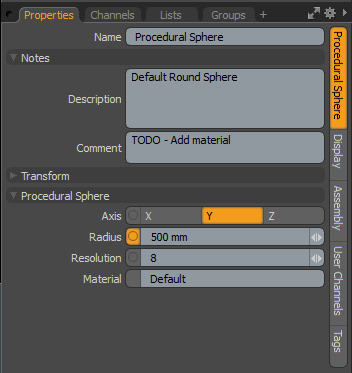
Tool properties only appear when a tool is activate, and they change depending on which tool is selected. For most tools, you can click and drag in the viewport, and see the properties update in real time. Conversely, you can directly edit the properties by clicking over a value and typing in a new value. Press Enter to see the update in the viewport.
Tip: You can press the Tab key to jump between value input fields.
Once you are satisfied with your settings, drop the tool by pressing the Space key.
For information about item properties, see Items (Scenes) List.
5 — Toolbars and Palettes
![]()
Accessing Tools
![]()
To gain faster access to a wide variety of Modo tools, click any of the toolbar buttons in the top-left corner of the interface. Once activated, the related tools are displayed in the Toolbox on the left panel. For example, click on the Game Toolbar and the related tools appear in the Toolbox.
![]()
In addition, when you select a different layout, the associated toolbar is displayed automatically. For example, open the UV layout and the UV toolbar is displayed on the left panel. You can click on any toolbar button to change the tools displayed in the left panel while working in the selected layout.
Toolbar Shortcuts:
• Hold Alt+click a toolbar button to open as a popover. Moving the popover pins it open.
• Hold Ctrl/Cmd+click to open it as a palette.
Accessing Common Palettes
![]()
To open a separate window for the Schematic palette, UV palette, Preview renderer, or Preset Browser while working in a layout, click on the palette's button.
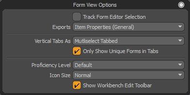
Form View Options
Pressing the O key in a form opens the Form View Options, where you can customize the appearance and content of the form.
>
|
Track Form Editor Selection |
When enabled, the form view displays what is currently selected in the Form Editor. |
|
Exports |
When a form's Exported option is enabled in the Form Editor, the form can be selected in a form view. This is also indicated by the X column in the tree. This dropdown lists the forms with Exported enabled. Selecting one displays it in the form view. |
|
Vertical Tabs As |
Select how vertical tabs are displayed. The following options are available: • Tabbed - Tabs are on the right, with one tab selectable at a time. • Multiselect Tabbed - Tabs are on the right, and you can select multiple tabs at the same time by Ctrl+clicking them. • Merged Tabbed - All tabs are merged into a single scrolling form. The tabs remain visible on the right and can be used to jump to different parts of the form. Tabs that are visible are drawn as selected, and change as you scroll the form. • Merged - All tabs are merged into a single scrolling from and the tab bar is hidden. |
|
Only Show Unique Forms in Tabs |
When enabled (the default), this hides subsequent references to the same sub-form when in a Merged or Multiselect mode. This helps to avoid redundant controls, such as the Name field at the top of many Item Properties forms. |
|
Proficiency Level |
This option is used to change the level of detail displayed in the form. • Default - Uses the Base Form Proficiency Level preference in the form. For more information, see Defaults Preferences. • Basic - A short list of the common core properties. • Standard - A list of all of the core properties. • Advanced - A list of all of the core properties plus custom functions for special behaviors. |
|
Icon Size |
Override's the form's default icon size with a custom size. Normal uses the icon size set in the form itself in the Form Editor. The following other options are available: • Extra small Icons • Small Icons • Large Icons |
|
Show Workbench Edit Toolbar |
Enabled by default, when there are any Workbenches in the form, this shows/hides their Edit toolbar. |
6 — Modo Modes

The Modes section can be found under the menu bar and above the 3D viewport. The first four buttons from the left are the Component editing modes, an important distinction in Modo. These modes set how you select and work directly with geometry for manipulation: pushing, pulling, and modifying polygons. You can toggle between any of these modes by pressing the Space key, continuously looping through them, or by pressing the numbers 1, 2, or 3 on the keyboard.
To enable Items mode for editing items, deselect the component editing modes. To understand the difference between Component modes and Item mode, think of each item layer as a container: the Component modes edit what's inside the container, and Item mode edits the container itself. A separate Item mode is necessary for some functions in Modo. For example, when animating, you are transforming items (the containers), and individual vertices are not directly animateable. Also, Replicators and Instances work by duplicating the container.
You can set an item's Center Selection and Pivot Selection points. These are the defined surfaces within the Shader Tree, which is the heart of Modo's shading system.
If you click the Set Polygon Tags ![]() button , a pop-up reveals additional material selection modes. For more information, see Polygon Set Material/Part/Smoothing.
button , a pop-up reveals additional material selection modes. For more information, see Polygon Set Material/Part/Smoothing.
The rest of the buttons are modifiers for tools, changing their basic behaviors:
• Action Centers - Automatically adjusts a tool's axis and orientation. For more information, see Specifying Action Centers and Falloffs .
• Symmetry - Duplicates manipulations across an axis. For more information, see Symmetry Tool.
• Falloff - Controls the effect a tool has on a selection based on an interactively applied distance. For more information, see Using Falloffs.
• Snapping - Eases certain workflows that require levels of precision. For more information, see Applying Snapping.
• Work Plane - An interactive and modifiable virtual workbench that simplifies many modeling tasks among other things. For more information, see Using the Work Plane.
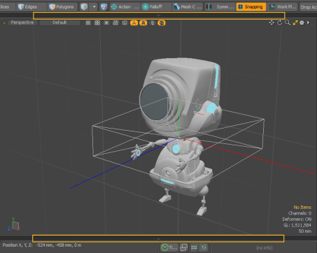
7 — 3D Viewport
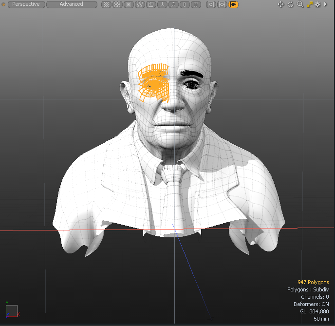
The 3D viewport is the most frequently used interface in Modo. It contains a dark grid going off into the distance. This is the ground plane, denoting the zero position of the Y axis. As items move up, they increase their Y position value.
Note: The Y axis is also referred to as the Up axis.
The X values move from left to right, and the Z axis (depth) moves from front to back. (If you are used to an alternate Up axis, you can modify the setting in System > Preferences) The darkest lines represent zero for the X and Z planes, the origin is where all three axes intersect, '0,0,0' on all three axes. Item level transforms all take place from this position.
The lighter grid is the Work Plane, the virtual desktop within the viewport. It interactively changes position based on the current viewpoint's position. For example, if you select the Cube tool and click and drag over the viewport, the first plane of the cube originates on the work plane itself. Drop the tool and rotate your viewpoint until the Work Plane changes position and then activate the Cube tool again and draw another square. This time it originates from the new Work Plane position. Based on your viewpoint, the Work Plane always tries to face the user, and appears within the viewport as a reference to where new items are created.
If you're used to working in a four-viewport system where you can easily place items in 3D space by moving them around in each viewport, the Work Plane allows you to work in a single large perspective viewport, and easily position items within the scene without surprises as to where items are created. There are several functions for modifying the Work Plane's position and how it adapts to the viewport, covered more fully in the Work Plane section.
You can navigate in the viewport using the three icons in the upper right-hand corner, or keyboard shortcuts.
• To move the viewport position, drag over the Four Arrows ![]() icon, or hold Shift+Alt while clicking and dragging in the viewport. Middle-click to move the view forwards and backwards, and right-click to restrict the view change to up and down.
icon, or hold Shift+Alt while clicking and dragging in the viewport. Middle-click to move the view forwards and backwards, and right-click to restrict the view change to up and down.
• To rotate the view, drag on the Rotation ![]() icon, or hold Alt and click and drag over the viewport. Middle-click and dragging restricts the rotation around the Y axis, and right-click and dragging flicks the view: it slowly stops when the button is released instead of directly stopping.
icon, or hold Alt and click and drag over the viewport. Middle-click and dragging restricts the rotation around the Y axis, and right-click and dragging flicks the view: it slowly stops when the button is released instead of directly stopping.
• To zoom in, drag on the Magnifying Glass ![]() icon, scroll the mouse wheel, or hold Ctrl/Cmd+Alt and click and drag in the viewport. Right-clicking and dragging defines a rectangular area that, when the button is released, Modo instantly zooms to.
icon, scroll the mouse wheel, or hold Ctrl/Cmd+Alt and click and drag in the viewport. Right-clicking and dragging defines a rectangular area that, when the button is released, Modo instantly zooms to.
8 — Items List, Mesh Ops, Shading, Groups, and Images
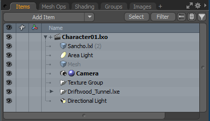
The top right area of the interface lists all the items that make up a Modo scene. These lists are important to the overall Modo workflow, so they appear in nearly all the various workspaces with some variation. The tabs across the top of this section filter which items are listed, grouped by how Modo sees them.
The Items list shows all the items that make up the scene, such as geometry layers, cameras, and lights. Within the list, items can be grouped together by parenting for organization or for animation Hierarchy. Selecting the various items displays their properties in the Properties viewport along with numerous other functions. For more information, see Items (Scenes) List.
The Shader Tree organizes all the surfaces within the scene and their respective items, such as materials, shaders, textures, and groups. When rendering a scene, it is the Shader Tree that controls how the final rendered image appears. For more information on these workflows, see Shading and Lighting and Rendering.
The Groups Viewport is useful for creating groupings of items in a scene, making it easier to select and manipulate multiple items, as well as for controlling lighting (light linking), making multi-item Replicators and for working with animated scenes when setting keyframes.
The Images tab lists all the external images currently loaded into Modo and offers functionality for working with them.
Note: Images aren't saved in the Modo file itself, so they need to be available each time a scene is loaded.
Lastly, the Quick Tips viewport offers some shortcuts to videos and such for quickly getting up to speed with Modo.
9 — Properties, Channels, Display, and Lists
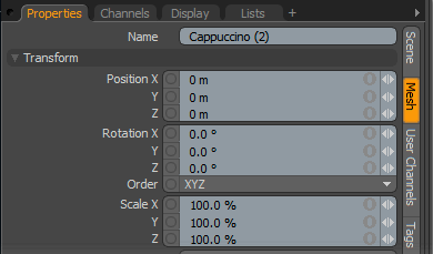
Directly below the Items list and the Shader Tree is another panel of lists. As scenes fill up with items, textures, UV maps, and so on, a serious amount of information is created along with it, and Modo offers many ways of viewing and manipulating all that info. In this group of lists, Properties is the most important. It is useful to keep this open most of the time.
The first tab across the top is the item Properties tab. Every item in Modo has a series of attributes associated with it, and this is the viewport where you can edit them. Selecting any item displays the item's properties, dynamically changing as different types of items are selected.
The next tab is Channels. Every animateable attribute of an item is listed here for easy view, selection and manipulation. For more information on the Channels tab, see Channels Viewport.
The Display tab controls the visibility and display of items in the 3D viewport. For more information on this tab, see Display Viewport.
The next tab, Lists, consists of three parts. The top section lists all the associated Vertex Maps. A Vertex Map is an instruction associated with a vertex telling it to do a certain thing, such as move a specific offset distance (morph map), specify a 2D position on an image (UV) or simply a value that is fed into another function such as Weight Maps do. To see the Vertex Map associated with an item, the item must be selected (highlighted in the item list). In this window, you can create, rename and delete any of the various maps.
Under the Lists tab is the Pipeline viewport or Tool Pipe. This is the heart of the Modo toolbox. A tool can be made up from a single function like the Cube tool, or it can be a combination of functions rolled together, such as a transform tool with a certain falloff and action center, like the Flex tool. The Tool Pipe is where you can make custom tool combinations. Presets contains the various pre-made tool combinations included in the various tool boxes that install with Modo.
Below the Pipeline viewport, you can find Statistics. This is a listing of scene statistics: the total number of polygons, how many of them are triangles or have more than 5 sides. You can use the +/- icons preceding each line for selecting and deselecting geometry in the scene based on the specific criteria.
Lastly, the Info tab gives you all the information associated with a selection. Selecting an item provides information on that item. Selecting some geometry provides information on all the associated vertices and map values as well as applied surfaces and selection sets associated with it. For more information on the contents of these tabs, see Info and Statistics.
10 - Kits Menu
The Kits menu is used to manage the visibility of kit icons and buttons displayed in the toolbar.
Tip: Modo Kits can be installed by downloading them from the Preset Browser's Cloud Assets > AddOns > Foundry > Kits directory. For more information, see Preset Browser.
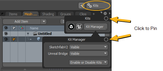
To hide or view kit icons and buttons:
• Click the dropdown menu beside one of the kits listed and select one of the following options:
• Visible - Shows the kit button on the toolbar.
• Hidden - Hides the kit button from the toolbar.
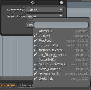
To enable or disable kits:
| 1. | At the bottom of the Kits popover, click Enable or Disable Kits. |
Note: Modo Kits are not removed from your system.
| 2. | From the dropdown menu, click on the appropriate kit to enable or disable. |
A check mark is displayed for the kits currently enabled. A (disabled) tag is displayed for the kits disabled.
Note: You must restart Modo after enabling or disabling any kit. Once done, the Kits menu is updated.
Layout Switching
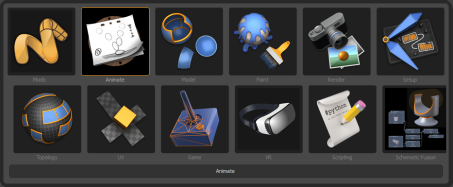
Modo employs an interface switching option using Shift+Ctrl+Tab to quickly switch workspace layouts. Press Shift+Ctrl and then Tab to open the selection pop-up. Continue to hold Ctrl and then release and press Tab again to cycle to the next workspace highlighted by the orange outline. Subsequent Tab presses continue to cycle through the selections organized by the layout's most recent use. Releasing the keys opens the currently selected interface. This method eliminates the space used by the tabs in the interface.
You can also open the Layout Switcher from the lower toolbar, by clicking Layouts. This option is also available from the menu bar, in Layout > Recent Layouts.... Specific layouts are accessible from the menu bar under Layout > Layouts. Each of the various workspaces is covered in more details below. Additionally, you can access the pie menu version of the Layout Switcher by pressing Ctrl+~ (tilde).
Layouts
Animate
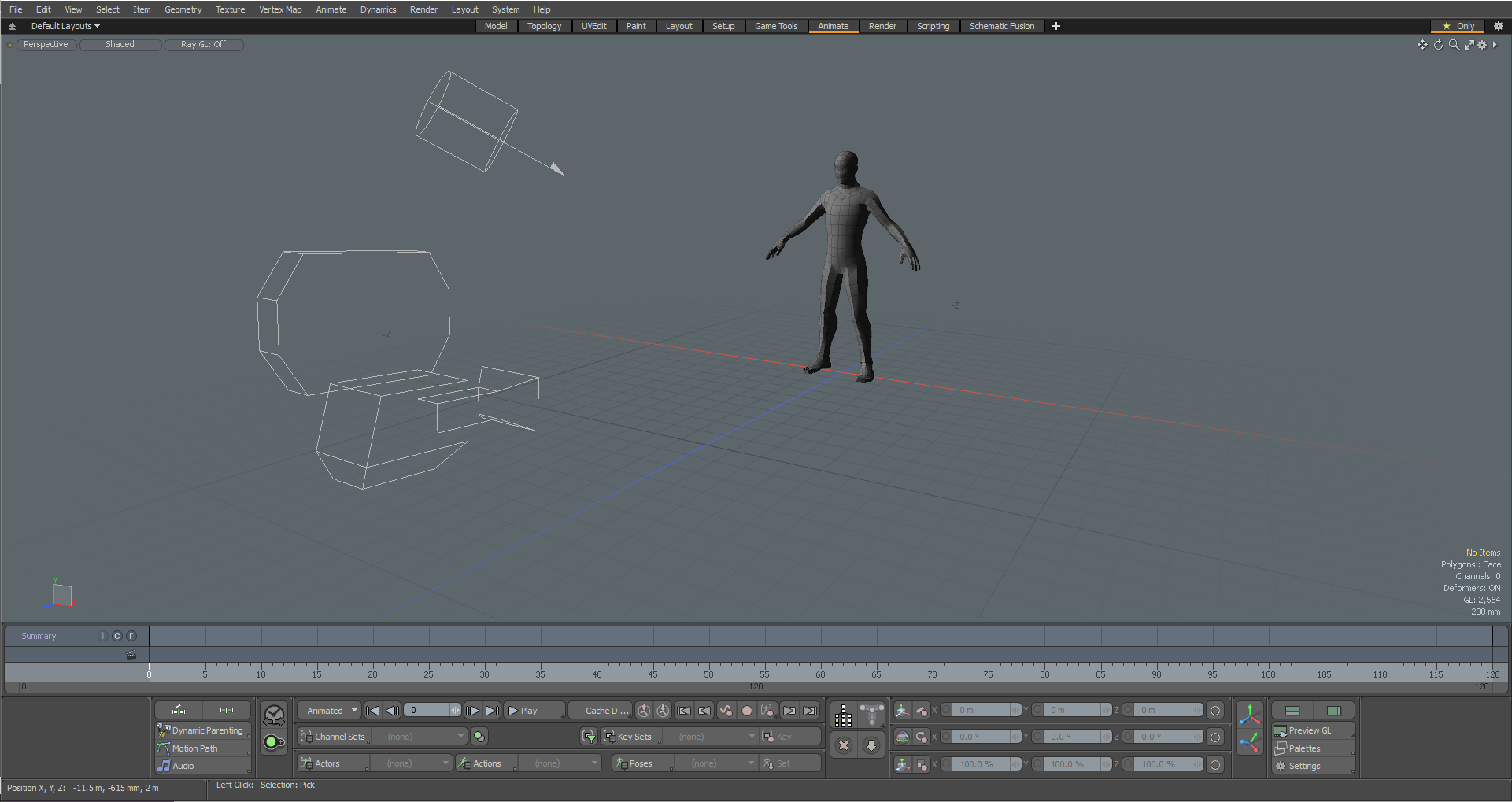
The Animate tab focuses specifically on animation, especially refined for character work. This viewport is unique in that the standardized layout is gone, in order to maximize the 3D viewport. Toolboxes have been reduced to pop-up palettes with the essential keying tools laid out as a special toolbox below the Timeline. Hidden just above the Timeline is the Track View that allows you to easily re-time animated elements. To open it, drag the top frame edge of the Timeline upward revealing the hidden viewport. Timeline playback controls run across the bottom of the interface with additional controls for setting keyframes and controlling the auto keying feature with additional easy access to the Channel Sets and Actor/Pose functions. For more information on the Animate viewport, see Animation Layout and Viewports.
Tip: If you are used to animating in previous versions of Modo, you can use the Layout and Setup interfaces with the more familiar controls.
Game
The Game layout provides you with a flexible structure, which makes it suitable to be used as your primary layout. The center of the layout is divided into a 3D viewport, a preview viewport, and a schematic viewport. The panels on the left and right are easily collapsible, and the toolbar on the bottom gives you quick access to a wide range of tools. For more information on this layout, see Game Layout.
Model
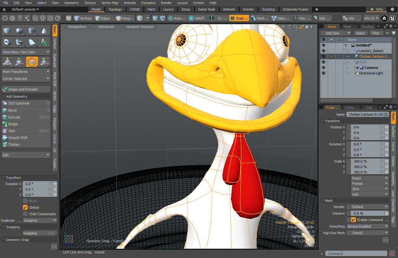
The Model interface is the dedicated model creation space, with all the creation and deforming-specific tools close at hand in the Toolbox on the left side. Below the Toolbox is the standard tool Properties panel. The middle section is the maximized 3D (OpenGL) viewport, where you can interact with the tool handles and selected geometry. The right side panel contains all the lists viewports: the Item List for selecting item layers in a scene, the Lists viewport with access to Vertex Maps, the Pipeline for customizing tools, and finally the Statistics viewport that allows statistical selections based on component features.
Modo
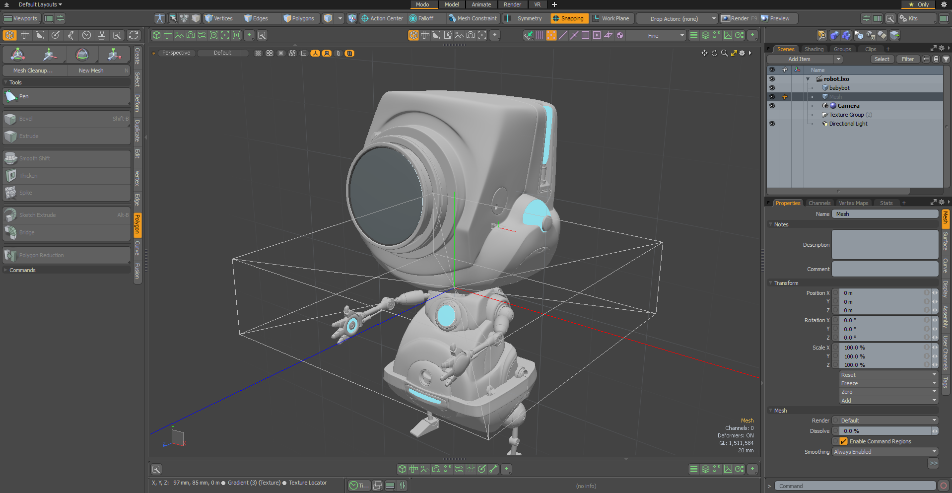
The Modo layout is an all-purpose interface that allows you to do virtually any task Modo is capable of. In the Toolbox on the left, you can find all tools arranged into sub-tabs. In addition to the tabs familiar from the Model layout, there is a Select sub-tab containing all selection tools.
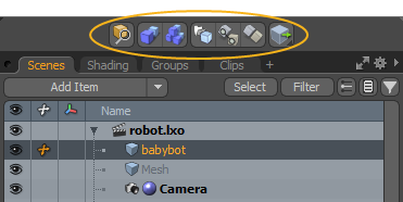
The buttons above the right panel are context-sensitive, and change depending on what tab is active. For example, opening the Scenes tab displays controls for duplicating, instancing, parenting, and grouping items.
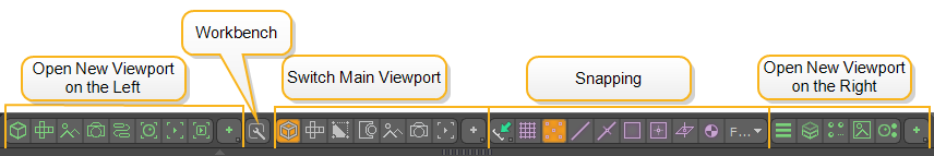
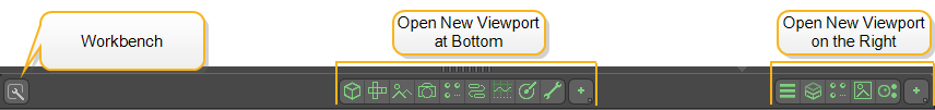
This layout has a collapsible area at the top and the bottom. To open them, click the thin line at the top or the bottom of the 3D viewport.
When expanded, additional controls appear that allow you to open more viewports. These areas are also equipped with workbenches, so you can add additional tool controls here. For more information, see Form Workbenches.
Top area:
Bottom area:
Paint
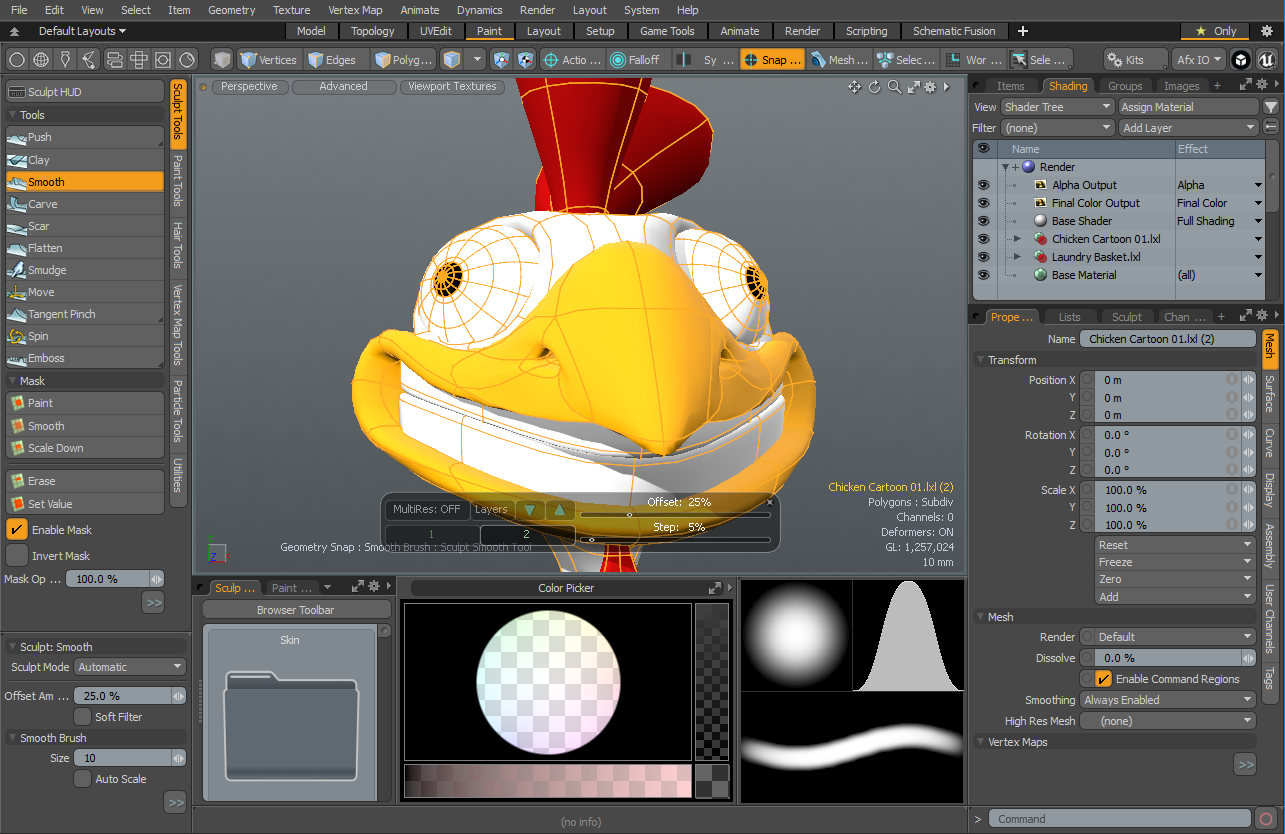
The Paint interface tab focuses on painting and sculpting. The left Toolbox is separated into the various tools and controls for painting textures and sculpting meshes. Directly below the 3D viewport is located a Preset Browser for viewing brushes and preset tool options. You can also directly access a Color Picker viewport and see the details of the current brush tip in the Tip View window.
Render
The Render layout provides streamlined access to the main options you need when focusing on the task of rendering a project. On the right-hand side is the Item List and Shader Tree panels, stacked with a tall Render Properties panel, so you can easily access and edit the various material and texture items and settings. The main 3D workspace is split into two views; a Preview Viewport that provides an extremely fast near final preview of the rendered scene, and a Camera View providing direct control over the positioning of the camera. To render in this view, press F9 or select the Render command from the Render options of the menu bar.
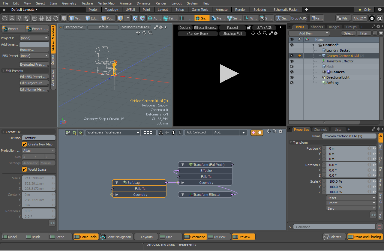
Schematic
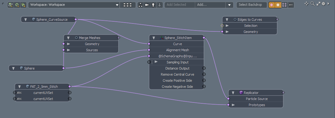
The Schematic layout allows you to set up symbolic relationships between items and their channels. It is a 2D environment where elements are visually linked, providing a more intuitive and powerful way to define relationships between elements; building networks of operations that are combined to produce a specific result.
Tip: You can also open the Schematic layout as a separate viewport by clicking the Schematic palette icon on the top-left corner of the interface. ![]()
Setup
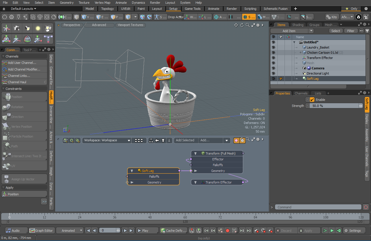
The Setup layout is mainly designed for rigging using the Schematic Viewport. You can select items in the Items list and Shader Tree, grab their associated channels in the Channel list and drag them into the Schematic View for node linking. The Toolbox also offers commands related to channel links and modifiers. Additionally, this is the place for setting up dynamics and particle simulations.
Topology
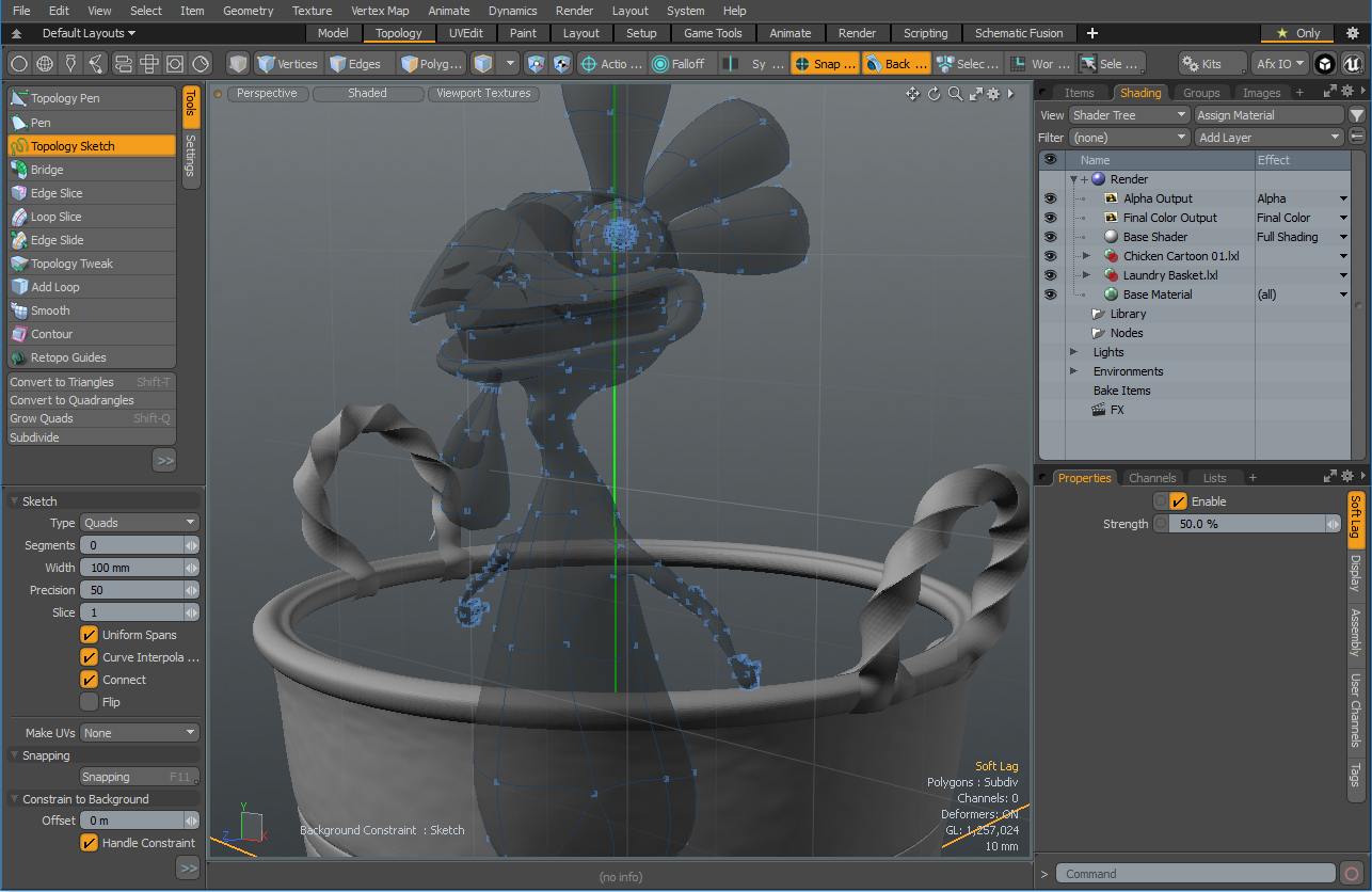
The Topology interface tab contains all the retopology related tools. Retopology is the act of taking a very dense (high resolution) mesh and using its surface in the background as a constraining surface to build a clean, lower resolution mesh. This is a common task when creating game assets where low polygon counts are a requirement, also when cleaning up scanned mesh data for animation, or when simply making it easier to change the topology and polygon flow of an existing model. The Toolbox contains tools that automatically conform to any item in the background, with a special OpenGL drawing mode to make it easier to see what is being drawn in the foreground over what is located in the background.
UV
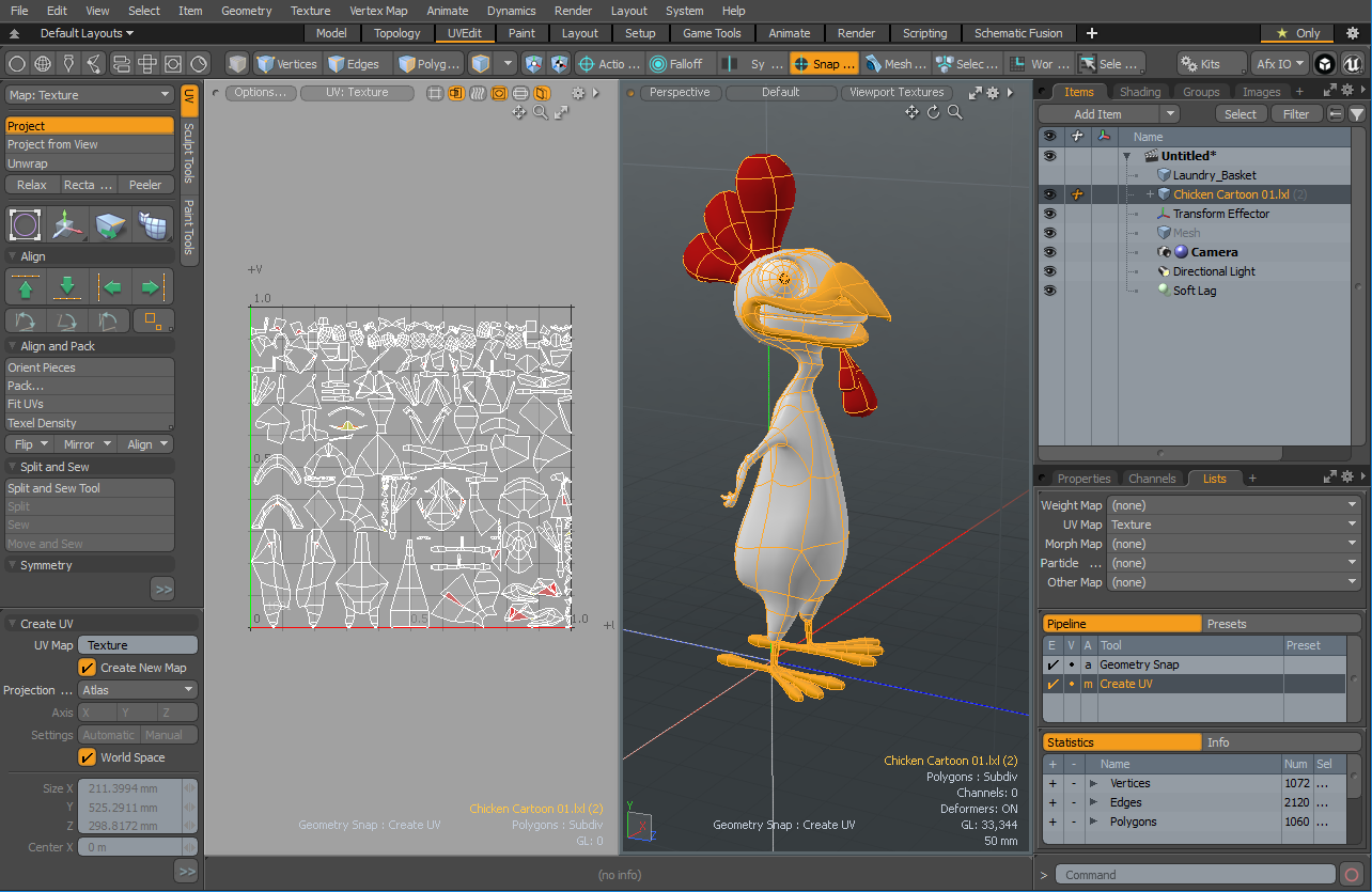
The UV interface splits the 3D viewport vertically adding a UV View on the left. You can select from the various maps in the Vertex Map list on the right-hand side. The Toolbox focuses on the various UV Mapping and editing tools.
Tip: You can also open the UV layout as a separate viewport by clicking the UV palette icon on the top-left corner of the interface. ![]()
For more information, see UV Viewport.
VR
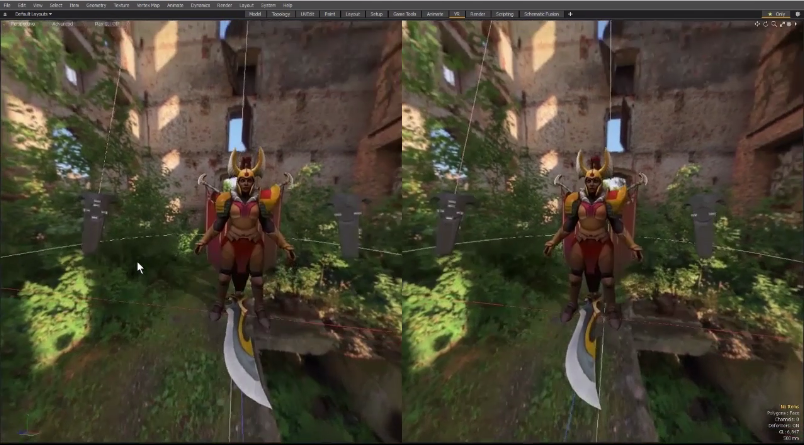
The VR layout allows you to create content using virtual reality technology to interact with a scene in a real time 3D environment. By using Modo as your full 3D modeling and animation software with a Head Mounted Device (HMD), you can step inside the scene to move your models around, scale your scene, add annotations, save camera shots, teleport yourself from one position to the next and apply commands such as actions, using the HMD controls. Modo allows you to return to the desktop experience to fine tune your models and animations.
Opening the VR layout initializes a connected VR headset and allows you to immediately view and adjust your model within a virtual environment. In this layout you can complete item transformations, scene layouts, and design reviews.
For more information, see Modo VR.