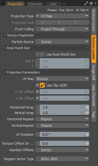
Texture Locator
When any texture layer is created in the Shader Tree, image-based or procedural, an associated Texture Locator item is automatically generated and added to the Items list and linked by the texture layer's Locator property. By default, texture locators are generally added to a folder (really a group locator item) called a Texture Group. This makes it easy to toggle the visibility of the locators in the 3D Viewports, as you might find them distracting. You may select the Texture Locator directly in the Items list, or by selecting the locator icon in any 3D viewport. Most often though, you select them in the Shader Tree. When any texture layer is selected in the tree, the Locator is available in the named sub-tab on the right side of the item's associated Properties panel. Additionally, the locator may be toggled by the small + sign preceding the texture layer's name in the Shader Tree; clicking the + button reveals the layer.
Texture Locators provide a very important function, as they control the application of the texture layer over the rendered surface. A Texture Locator is like a regular Locator Item, in that it has Position, Rotation, and Scale information. Additionally, there are settings specific to controlling the image's projection method, meaning how it is mapped or applied to the surface. For certain projection modes, such as Planar, you can interactively position textures in the 3D viewport by transforming the Texture Locator item itself. Other modes, UV in particular, completely ignore the positional and scale attributes, as the mapping is defined by the UV map itself.
Texture Locator Properties
|
Projection Type |
A projection defines how a texture, be it image-based or procedural, is applied to a dimensional 3D surface. The various projection types can greatly affect the final rendered outcome. Modo offers a variety of projection types (illustrated in Projection Type Samples). |
|
Projection Axis |
Defines an axial direction for any of the primitive projection types: Planar, Cylindrical, Spherical, Cubic, Box, and Light Probe. |
| Front Culling |
Creates a texture shadow that only maps the parts of the geometry directly seen by the camera. The following options are available: • Project Through - Projects the texture on the back faces of the mesh. • Cull Backfacing - Projects the texture only on the front of the mesh. • Flip Backfacing - Projects and flips the texture on the back of the mesh along the U and V directions and appears upside down. • Flip U Backfacing - Projects and flips the texture on the back of the mesh along the U direction only and appears upside down. Flip V Backfacing - Projects and flips the texture on the back of the mesh along the V direction only and appears upside down.
|
Texture Replicator Properties
|
Particle Source |
You can specify a Mesh item layer as a point source for the cloned textures, when doing so, the Texture Replicator option is effectively enabled and its settings supersede all others of the Texture Locator. Once a mesh layer is defined, a single copy of the texture is positioned and aligned to the vertices normal at each vertex point. Typically, you would specify the mesh layer of the actual target surface with this option. However, interesting effects can also be obtained when specifying alternate mesh layers. Keep in mind that the clones are aligned to the surface normal of the source mesh, so surfaces would need to be in somewhat close proximity and need to have similarly facing normals. |
Real World Size
|
Use Real World Size |
Enable to use the real world size for this texture. Some textures, such as AxF material textures, are imported with a real world size, which is set automatically in the Size X and Y fields. You can also specify the real world size of the texture manually using the Size X and Y properties. Note: You must have real world size assigned to the selected UV map in order to enable this property. See Adding Real World Size to UV Maps for more information. Tip: Modo's USD import functions also support UV tiling Real World Size information in the Texture Locator tool's properties viewport. |
|
Size X |
The real world size of the texture in millimeters or meters along the X axis. |
|
Y |
The real world size of the texture in millimeters or meters along the Y axis. |
Transform Properties
|
Position |
An Item transform that allows you to numerically position the texture locator item in XYZ space, thus defining the position of the projected texture. This position defines the center of the texture's overall volume as defined by the Size setting. Useful in the positioning of textures when using standard projections such as Planar, Cylindrical, and Cubic, among others. You can automatically define a texture's Position and Size using the Auto Size function. |
|
Rotation |
An Item transform that allows you to numerically set the rotation of the texture volume. The Rotation transform originates from the locator item's position value. |
|
Order |
Sets the order that rotations are applied to the Locator Item. Changing the order that rotations are applied can sometimes help to reduce or eliminate gimbal lock when animating. |
|
Size |
Sets the textures projection size (or boundary, as the case may be), defining the texture's overall volume. You can automatically define a texture's Position and Size using the Auto Size function. |
|
Auto Save |
Automatically sets the Position and Size values, and is determined by the overall bounding box volume of the tagged surface(s). |
|
World Transforms |
Typically, if you move a texture locator around, the texture moves over a surface that is sitting still. This allows for animated textures. If you parent the texture locator to the item and move the item around, both are moving in sync, so the texture stays still. With World Transforms enabled, the parented texture animates over the surface, as if the surface was sitting still and the locator was moving by itself. It's a subtle difference to World Coordinates. |
|
World Coordinates |
Typically, if you move an item, the texture moves with it, as if painted on. When World Coordinates is enabled, textures act as if frozen in place, with surfaces swimming through the texture. This option is extremely useful for texturing cloned or replicated items with procedural textures (that are NOT animated) as it provides the look of randomizing the texturing, without the need to modify any other surface attributes. |
Projection Parameters Properties
|
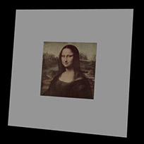
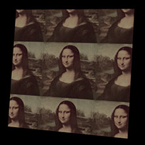
Horizontal/Vertical Repeat |
Sets how bitmap images repeat beyond the defined image size/UV space boundary. Several methods can be chosen: Reset disables image tiling, Repeat tiles repeatedly, Mirror tiles the image, flipping each subsequent image to produce a backward and forwards type tiling, and Edge simply repeats the edge row of pixels. You should note that these options are not visible in the GL Viewports.
|
||||||||
| UV Rotation |
Rotates the image plane relative to the UV space, eliminating the need to rotate the UV mapping values manually. Rotation revolves around the 0,0 UV origin. |
||||||||
| Texture Offset Strength |
Determines the global strength of both the Random Offsets option, when one is defined, and for the layer effect Texture Offset. A value of '0.0' produces no offset, a value of '10.0' is offset up to 100% of the original location. When using both the Random Offsets and a Texture Offset Strength effect, the offset effect can be controlled independently by changing the texture layers opacity. |
||||||||
| Random Offsets |
Controls the relative positions of bitmapped textures on a surface based on the designated criteria. Working best with tiling textures, where there would be no distinct seam across edges, this option helps to hide or eliminate repetition by moving the texture a random direction across the surface. The amount of offset is determined by the Texture Offset Strength option. The different offset criteria can be based on: • (none) - disables the Random Offset feature when selected. • Particle and Replicas - offsets are generated per particle and/or per Replicator item. • Mesh Parts - offsets are generated based on individual mesh parts: multiple, individual geometric objects within a single item layer. • Surfaces - offsets are based off discreet sections of a single, named surface across continuous geometry. |
||||||||
| Tangent Vector Type |
Determines the tangent vector basis for an associated image map set as the surface normal, affecting both the baking and the display of normal maps. Normal maps are generally baked from high resolution geometry onto low resolution geometry to give the impression of higher resolution. There are two options available: dPdu dPdv defines a tangent space normal, the dPdu Cross Product option defines a bi-tangent space normal that is compatible with many game engines. When baking image-based normal maps, you need to define the proper vector basis prior to actually baking the image out for the proper results. |
Falloff Properties
|
Falloff Type |
Fades the texture layers opacity over the specified distance. There is cubic (3D), spherical (3D), and Linear X, Y, or Z. For more information, see Using Falloffs. |
|
Falloff X/Y/Z |
A setting of '0' disables falloff. The falloff amount act like a multiplier of the size. So a setting of 0.5 on a 1 meter texture scale fade the texture to fully transparent over 2 meters from the locators position, a setting of 0.1 would scale it to fully transparent at 10 meters. |