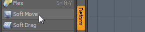
Model the Mug
To get started, let's model a simple object: a Modo coffee mug. Don't worry if you haven't used Modo before, this is a good starting point.
The video below shows you how to model the mug. It covers the creation of a basic cylinder through to advanced polygon manipulation. The written tutorial includes background information for those new to 3D modeling, although you can choose to follow the video instead.
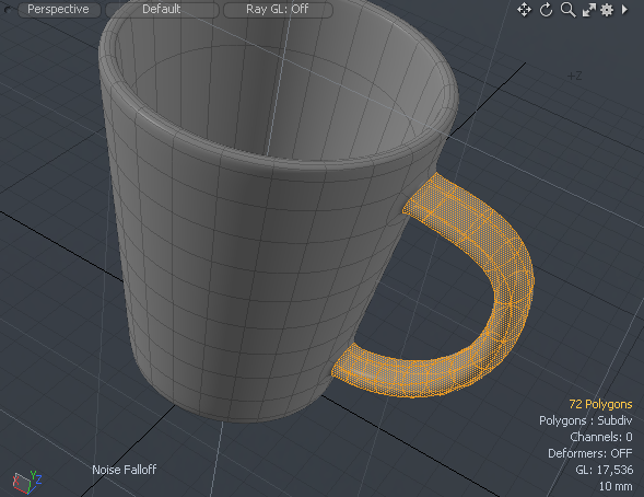
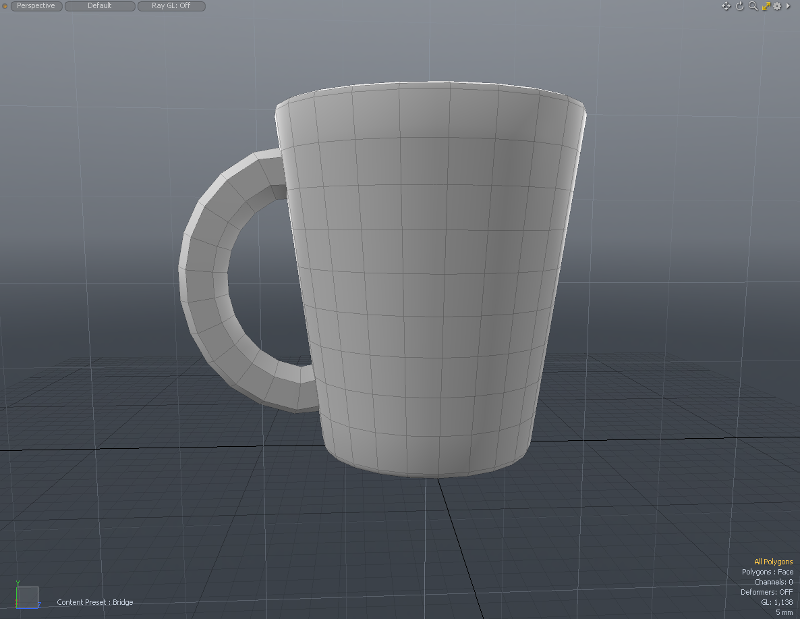
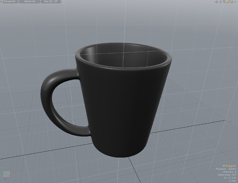
Here's a picture of the mug that we'll model.

This part of the tutorial shows you how to model the shape of the mug, including the handle. If you've already done this, you can skip to the Render the Mug to create the surface detail and produce the finished render.
As you become familiar with Modo you'll find there are different ways of achieving the same result. However, the methods described here demonstrate key features that you'll reuse in other projects.
If you're brand new to Modo, it may help to take a look at Exploring the Layout to discover how the interface is organized. To find out how to interact with Modo, you can read User Interface Conventions. You can also find a quick introduction to modeling concepts in Modeling Overview and Techniques. Reading these aren't compulsory, but recommended if you're new to 3D modeling.
Setting Workspace, Layout, and Viewport
Reset the Workspace
If you've just opened Modo, the you can start the tutorial with the default configuration. If you've been trying out the interface, it's a good idea to reset the workspace to the default (base) configuration. This guarantees that we're starting from the same place.
You can also reset the workspace if you run into trouble during the tutorial and want to start afresh.
To Reset the Workspace:
| 1. | Select File > Reset. |
You'll see a prompt asking if you want to restore the layout to its base version.
| 2. | Click OK. |
Choosing the Model Layout
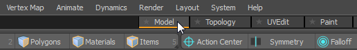
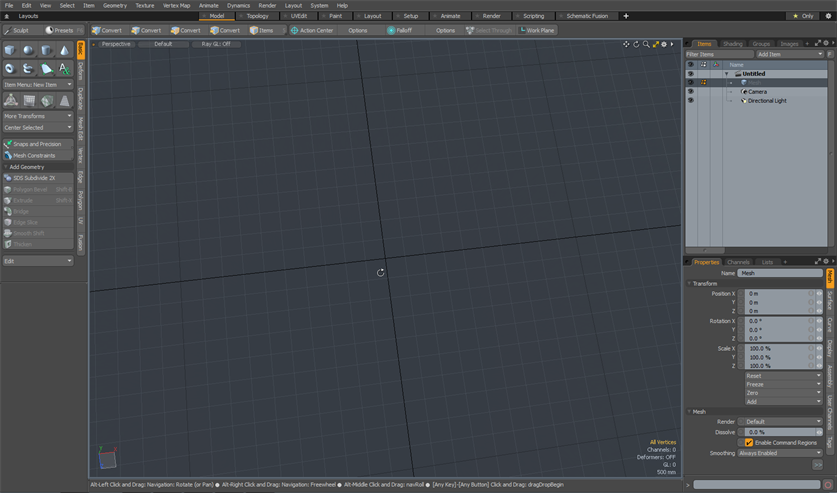
Modo offers multiple interface layouts, each with a toolset targeted at a particular task. Layouts are selected using the tabs directly under the menu bar. For this tutorial, we'll use the Model layout. This layout is designed for creating 3D objects using object primitives (simple shapes), and it provides a large perspective view of the scene.
Note: In the Perspective view, you see objects in three dimensions as you would in the real world. It's just like viewing the world through a camera viewfinder; you see the world in a rectangular window (viewport) and you can move the camera in space to see objects from a different position.
To Choose the Layout:
| 1. | Click the Model tab on the switcher bar. The switcher bar is below the menu bar at the top of the application window. |
| 2. | If you can't see the switcher bar, it may be hidden. Click the dark line below the menu to reveal the switcher bar. |
OR
| 1. | Select Layout > Layouts > Model. |
Tip: You can also select a layout using Modo's layout switcher. Press and hold Shift + Ctrl/Cmd, then press Tab to open the switcher. Keep pressing Tab until you highlight the chosen layout, and release both keys to use the layout.
Introducing the 3D viewport
Most of your work in Modo is done in the 3D viewport. This is a window onto 3D space that you can explore by rotating, panning and zooming. The viewport has several visual cues to help you build objects and find your way around.
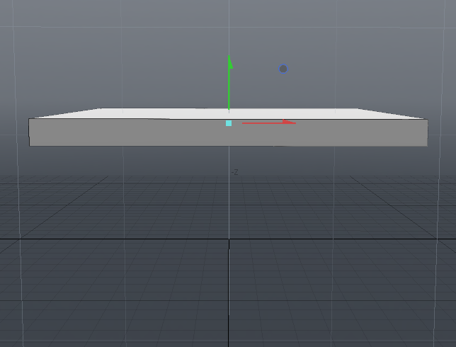
Any position in the 3D world is defined using values along three orthogonal axes: X, Y and Z. The X-axis runs horizontal from left to right, and the Y-axis runs up and down. These axes cross at the World Origin, where X = 0 and Y = 0. The addition of a third dimension introduces the Z-axis, which runs forward and backward through the World Origin.
An object's position in 3D space is identified by a given distance along each of the axes from the world center (or World Origin). For example, a sphere may be placed at X = 2 m (2 meters over to the right), Y = 1 m (1 meter off the ground) and Z = -3 m (3 meters behind the World Origin).
The diagram below shows the location of the axes and the World Origin as they appear in Modo.
Note: The yellow arrows are for illustration purposes only.
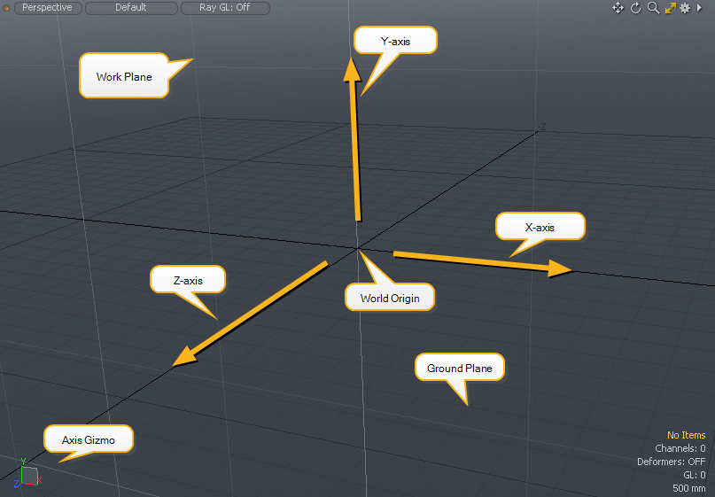
The image above shows the following elements:
• X, Y and Z axes: Modo draws the X and Z axes using thick black lines. The Y-axis rises perpendicular (at 90 degrees) to the point where the X and Z axes intersect. The X-axis values increase to the right, the Y-axis increases upward, and the Z-axis increases forwards. (The increase in values is shown by the direction of the yellow arrows.)
• World Origin: The point at which the axes intersect is known as the World Origin. This is the point where X = 0, Y = 0 and Z = 0.
• Ground Plane: Modo draws a dark-gray grid on the ground to help you orient the 3D viewport. This surface is the ground plane, or the XZ plane. (A plane is a flat surface in the 3D space.) The ground plane goes through all points in X and Z, where Y = 0.
You can think of a plane as a slicing through the 3D space. The ground plane slices through the space along all points where Y=0.
• The Work Plane: This is a light-gray grid that shows the plane on which new objects are drawn (see below). The Work Plane snaps to the facing plane as you rotate the view.
• Axis Gizmo: This graphic shows the current orientation of the axes in 3D space. The Gizmo rotates as you rotate the view. By checking the Gizmo, you can see at a glance how the axes are oriented and in which direction you are facing.
The Gizmo also shows the position of the Work Plane using a small square that is aligned to the appropriate plane.
Tip: To rotate the viewport, hold Alt, click and drag in the viewport.
To pan the viewport, hold Alt+Shift, click and drag in the viewport.
Try rotating and panning the viewport to become familiar with navigating the 3D space.
Introducing the Work Plane
The work plane is the surface on which you draw objects. This is an important tool in Modo as it helps you place objects in the world as you work. As you add objects to 3D space, it's useful to have control over how they are first placed, and how they are translated. For example, if you're modeling the inside of a room and want to add a poster, then it would make sense to first add the poster to the wall, and move it across the wall into the right position. In this case, we'd align the work plane to the wall. If you're adding a rug to the room, then it would be better to drop the rug onto the floor and move it along the floor plane, so the work plane should be aligned to the floor.
In Modo, the Work Plane automatically snaps to become parallel with one of the three dominant planes. A dominant plane is the flat surface that aligns with two of the three axes. For example, the XY plane is the flat surface that covers all points that extend left/right along the X-axis, and up/down along the Y-axis. The image below shows three squares, each aligned to a dominant plane.
Note: By default, the Work Plane snaps parallel to a dominant plane but it does not mean that it is always exactly in-line with each axis. For example, the Work Plane may snap parallel to the ground plane, but its height above/below the ground is adjusted to suit your viewpoint.
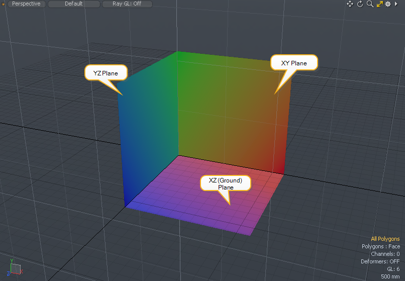
In Modo the work plane is shown as a light-gray grid. In the image above, the Work Plane is aligned to the XY plane. Try rotating the viewport and see how the work plane changes.
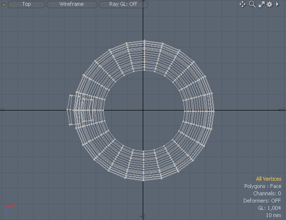
Drawing a Cylinder
Often in 3D modeling, we start with a simple shape and adjust it to resemble the main body of the object that is being modeled. Different parts of the object are then modeled separately to achieve the overall look.
If we look at the photo of the coffee mug, we can see the mug has two main parts, the body of the mug and the handle. We'll start by creating the mug body. The body itself resembles a tapered, hollow cylinder. So let's start by creating a cylinder that's standing on the ground plane. To do this, we'll first need to position the work plane.
Orientating the Work Plane and Drawing a Cylinder
To Orient the Work Plane and Draw a Cylinder:
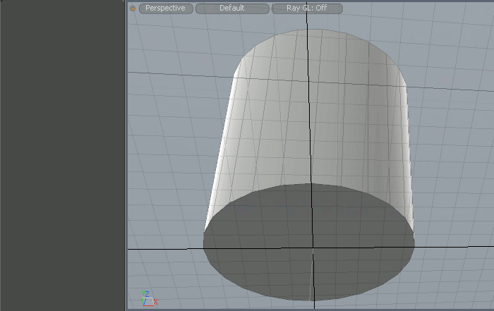
| 1. | First we need to make sure that we draw the cylinder base parallel to the ground plane. With the mouse in the 3D viewport, hold Alt and click and drag to tumble the view so that you are facing down toward the ground plane, with the origin close to the center of the viewport (as shown in the image below). |
The work plane snaps to the ground plane.
Note: The origin is at the intersection of the X and Z black axis lines.
Tip: The Modo window may lose focus if you interact with another window (such as this help). If so, you may find Modo doesn't respond to key presses. Click on a blank part of the Modo interface to regain focus.
Note: The Work Plane is used when you add or transform a primitive. It has no effect in interactive mode when you adjust the handles to change the shape or dimensions. You can also freely tumble and zoom viewports, and the movement of the Work Plane does not alter existing geometry.
| 2. | Click on the Cylinder tool |
When selected, the cylinder icon is highlighted in orange and its attributes appear in the tool Properties panel in the lower-left of the Modo window.
Note: If you see properties in the panel in the lower-left of the Modo interface (the Properties panel), it means that a tool is active. When active, you can edit the property values or use the mouse to manipulate the tool.
| 3. | Hold Ctrl/Cmd, click at the origin (in the viewport) and drag outward. |
Holding Ctrl/Cmd constrains the cylinder to be circular.
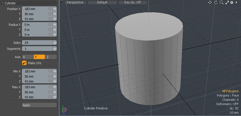
| 4. | In the tool Properties panel, set Sides to 24 and Segments to 1 (as shown above). |
Tip: To change a property value, edit the value and press Tab or Enter.
This creates a cylinder made up of 24 polygonal strips around the circumference, where each strip is a single polygon.
Tip: Try altering the value of Segments to see how the cylinder changes. As you increase the value, you'll see how more polygons are used to build the sides.
Sizing and Placing the Cylinder
Once placed, a primitive enters interactive mode and you can see the red, green and blue editing handles on the object. You can use the handles or edit property values to modify the primitive, and it updates immediately.
At the center of the cylinder there are three arrows for moving the cylinder, one for each axis. The red, green and blue arrows move along X, Y and Z respectively. The small, colored boxes on the surface of the cylinder are for adjusting the size along each axis.
Tip: You can see the axis colors and the current orientation in the bottom-left of the viewport:

We'll adjust the size of the cylinder to roughly match that of the mug, then we'll sit the base on the ground (XZ) plane. The mug is approximately 90 mm wide and 100 mm tall. For sizing the cylinder, Modo uses the Radius property, which is half of the full length.
Tip: Use Ctrl/Cmd+Z to undo. If you want to redo an operation, press Ctrl/Cmd+Shift+Z.
To Change Size and Position:
| 1. | Set the Radius X and Z to 45 mm and the Radius Y to 50 mm. Enter the values in the Properties panel or use the handles to resize the cylinder. |
Tip: If the cylinder appears small, use the mouse wheel to zoom. Use Alt+drag to rotate and Alt+Shift+drag to slide the viewport.
| 2. | Click the green arrow handle and move the cylinder upward onto the ground plane. The Min Y setting is the height of the lowest edge of the cylinder; drag the handle so that Min Y equals zero. Alternatively, you can enter 0 in the Min Y property. |
| 3. | To make sure the cylinder is at the world origin, set Position X and Position Z to 0. |
| 4. | Once you have set the values, press the spacebar to drop the tool. |
The properties and the editing handles disappear.
Tip: If a key press doesn't work when a tool is active, it may be that the tool properties intercept the key press and you edit a property unintentionally. If this happens, click anywhere on a blank area of the interface (not in the viewport) to shift focus away from the Properties panel, then retry the key press.
Drawing, Sizing and Placing the Cylinder - Quick Method
The instructions above are good practice for placing and sizing geometry. However, there is an alternative method which cuts out a few steps and is ideal if you want to place a primitive quickly. To do this, you first define the properties of the cylinder, including size and location, and draw the cylinder using the Apply button.
To Predefine and Draw the Cylinder:
| 1. | If you've been using Modo already, close the existing scene using File > Close Scene (or Ctrl/Cmd+W). |
| 2. | Click on the Cylinder tool icon in the Basic sub-tab of the toolbox on the left side of the screen |
| 3. | In the cylinder's Properties panel in the lower-left of the Modo interface, edit the properties as follows: |
Position:
• Position X : 0 mm
• Position Y : 50 mm
• Position Z : 0 mm
Tip: The Position parameters refer to the center of the cylinder. To put the cylinder on the ground plane, we need to set the Y-position to half the height, in this case 50 mm.
Size:
• Radius X : 45 mm
• Radius Y : 50 mm
• Radius Z : 45 mm
Polygons:
• Sides: 24
• Segments: 1
Orientation:
• Axis : Y
| 4. | Click the Apply button at the bottom of the Properties panel. |
If you can't see the Apply button, it may be that part of the Properties panel has been hidden due to lack of screen space. If so, you'll see a small double arrow ![]() button . Click this to reveal the rest of the Properties panel.
button . Click this to reveal the rest of the Properties panel.
Tip: If your cylinder is too far away or you are too close, press A to fit your object to the viewport. If A doesn't work, click on a blank area of the interface to shift focus away from the primitive properties and try again.
Working with Meshes, Layers, and Scenes
Introducing Meshes, Layers and Scenes
In the field of 3D modeling, you'll often hear the word 'mesh' used to describe 3D objects. A Mesh is the term given to the collection of vertices, edges and polygons that fit together to make up a 3D model.
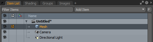
Whilst working in Modo, your 3D objects are stored in a mesh layer, which is shown in the Item List to the right of the workspace. A Layer acts as a container for each type of item (such as a mesh), and allows you to focus your work on the contents of the layer. Layers may contain items such as lights, or cameras, and if you want to edit these items, you can switch to the appropriate layer.
The collection of all the layers in a file is called a Scene. When you render your work, Modo draws the entire scene using the items in the scene's layers.
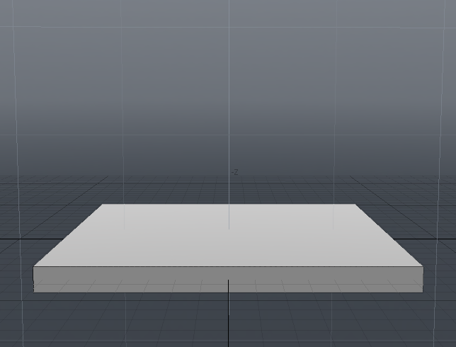
Tapering the Cylinder
To shape the body of the mug, we need to taper the cylinder so that the base is smaller than the top. The simplest way to do this is to shrink the polygon at the base of the cylinder.
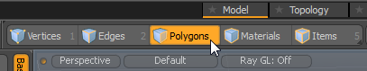
So far we've been working in Items selection mode, which applies operations to all of the geometry in the current mesh layer.
To manipulate individual polygons, we need to go into Polygons selection mode. You can then select a polygon by clicking on it.
Note: In any selection mode, unless you select something, Modo uses the implied selection, which is everything in the layer. For example, if you are in Polygons selection mode and nothing is selected, any transform you apply affects all polygons.
Note: Selections are highlighted yellow. You can deselect everything by clicking on empty space in the 3D viewport (when no tool is active) or by pressing Esc.
To select multiple elements, click and drag over the geometry. This is known as paint based selection.
To add to the current selection, hold Shift and click to select the element.
To remove something from the current selection, hold Ctrl/Cmd and click on the selected element.
Transforming Polygons
To Select and Transform a Polygon:
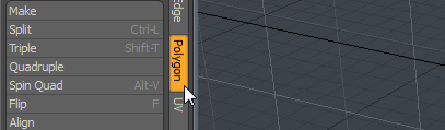
| 1. | Choose polygon selection mode by clicking Polygons on the modes toolbar. Alternatively, press 3 on the keyboard. |
| 2. | Tumble the viewport so that you can see the bottom of the cylinder. |
Tip: Before the next step, make sure there is no active tool. If you see parameters in the Properties panel (lower-left), press the spacebar to drop the tool.
| 3. | Click on the bottom of the cylinder to select the polygon. |
The polygon turns yellow.
| 4. | Click on the Scale tool or press R. |
![]()
The Scale tool handles appear in the center of the selected polygon.
| 5. | Click and drag the small green circle to scale both the Scale X and Z values simultaneously. Scale them to 70%. |
Tip: You can apply a transform equally in all dimensions by holding Ctrl and dragging one of the transform axes.
The small circles that appear in the scale tool also constrain the transform to be equal, but along a single plane.
| 6. | Press the spacebar to drop the Scale tool and return to selection mode. |
| 7. | Deselect the base by clicking away from the geometry in the 3D viewport. |
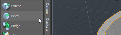
Beveling and Hollowing-Out the Cylinder
To create the interior of the mug, we need to add more polygons to the top of the cylinder so that we can drag down to create a hole. If we were to drag the top polygon as it stands, the entire mug would be flattened. To remedy this, we can use the Bevel tool to add an inner ring of polygons to the top.
We'll need to bevel twice. Once to create the rim of the mug, and again to create the inside base of the mug.
Note: You may have noticed that when the mouse hovers over a particular element, its color changes. This is called pre-highlighting, and it indicates that the element is selectable.
Tip: To apply a second bevel, we can drop the Bevel tool and add it again. However, Modo provides a shortcut. With the first bevel active, simply Shift click in the viewport to reset the tool and apply a new bevel.
Beveling and Adding an Interior
To Bevel and Add an Interior:
| 1. | In Polygons mode, tumble the viewport and select the top surface of the mug. |
| 2. | Select the Polygon sub-tab of the toolbox. |
| 3. | Click on the Bevel tool or press Shift+B. |
![]()
| 4. | With the tool active, click in the 3D viewport to enter interactive mode for the tool. |
The bevel tool has two handles, a blue one to offset the new polygon from the surface, and a red one to change its size.
| 5. | Click and drag over the red handle to scale the inner polygon until the first Inset value reads 5 mm. |
This creates the rim of the mug.
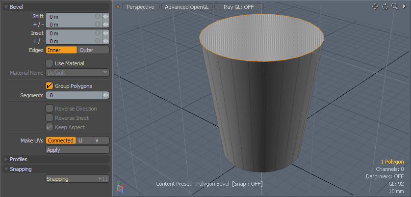
| 6. | While the tool is still active, hold Shift and click anywhere in the 3D viewport (away from any tool handles), to reset the Bevel tool. |
This adds another polygon within the rim.
| 7. | Click and drag the blue handle down to a Shift value of -95 mm. |
| 8. | Press the spacebar to drop the tool. |
| 9. | Activate the Scale tool by pressing R and use the green circle to scale the selection to 70%. |
| 10. | Press the spacebar to drop the tool. |
Note: You may have noticed that we could use Bevel Inset to scale the base polygon instead of the Scale tool. Since the bevel specifies the inset as a measurement, it's easier to match the inside base of the mug to the outside base by giving it the same scale value.
Beveling and Rounding Corners
The mug in the photo has nice rounded edges, unlike our model, so we need to round them using the Edge Bevel tool.
Since we only want to affect the edges at the corners of the mug, we need to select only those edges. The corners occur at the rim of the mug, inside around the base, and around the outside base. Once the edges are selected, we can apply the Edge Bevel tool to add more edges and create a rounding effect.
Selecting edges manually can be time-consuming. Luckily, Modo provides a number of ways to speed up selections.
To select all the edges around the border of an area of polygons, first select the polygons, then hold Ctrl/Cmd. You'll see that the Edges mode button becomes Bounds. With Ctrl/Cmd still held, select Bounds mode and the bounding edges are selected automatically.
Tip: To select all the edges in a loop, in Edges mode, select two adjacent edges and press L. Selecting two elements determines the direction of the loop. Loop selection also works for polygons and vertices.
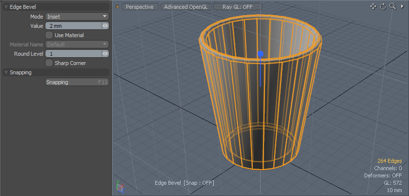
To Select Edges and Apply a Bevel:
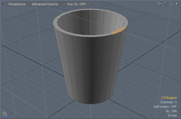
| 1. | In Polygons selection mode, select two adjoining polygons on the top rim by clicking and dragging over the polygons. |
| 2. | Press L to select the entire loop. |
| 3. | Rotate the view to see down inside the mug and Shift select the inside base of the mug. |
| 4. | Rotate to see the outside base of the mug. Shift select the bottom polygon. |
Tip: If you accidentally lose your selection, use Ctrl/Cmd + Z to undo and restore it.
| 5. | Hold Ctrl/Cmd to change the Edges selection mode button into the Boundary button. |
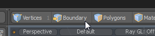
| 6. | Click the Boundary button to convert the selection and automatically enter Edges mode. |
| 7. | Select the Bevel tool from the Edge sub-tab of the toolbox. |
| 8. | Click in the 3D viewport to activate the tool's interactive mode. |
| 9. | Set Value to 2 mm with a Round Level of 1 as illustrated below. |
This makes rounded edges, similar to the original mug image.
| 10. | Press the spacebar to drop the tool and Esc to drop the selection. |
Saving Your Work
To save your work, select File > Save or press Ctrl/Cmd + S to open the save dialog. Name your file 'mug', and save it to a directory.
When you save, the scene name in the Items List in the upper-right of the Modo interface changes to the filename.
Note: When you open Modo, the scene is called Untitled by default, and a small asterisk is shown by the scene to indicate that it hasn't been saved.
Preparing the Surface
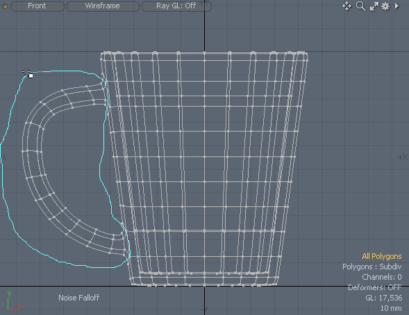
Now let's start to build the handle. You'd be right in thinking that we could model the handle as a separate object and join it to the body of the mug. Though possible, one of the drawbacks with that approach is that it makes it harder to guarantee one continuous smooth surface across the object. Instead, we'll add edges to the side of the mug so that we can grow the handle outwards from the body and preserve continuity.
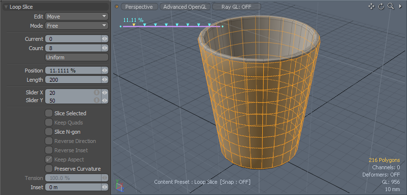
A quick way to add edges is with the Loop Slice tool. To use this we first need to select the surface polygons that we want to slice.
Note: We could have added the extra edges when making the cylinder. However, this would have made shaping the cylinder more difficult. If we started with more edges on the side, shaping the bottom polygon would only taper the single row of polygons above it, and not the whole cylinder.
Add More Edges:
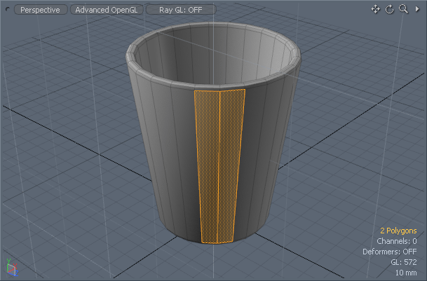
| 1. | In Polygons mode, select two adjoining polygon faces, this time on the side of the mug, and press L to select the loop. |
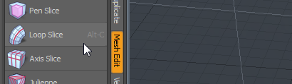
| 2. | Activate the Loop Slice tool from the Mesh Edit sub-tab of the toolbox, or press Alt+C to select the tool. |
| 3. | Click in the 3D viewport to activate interactive mode. |
By default, this draws a single slice halfway up the side of the mug.
| 4. | We want 8 slices; in the tool properties, set Count to 8. |
| 5. | Drop the tool and the selection. |
Adding Action Centers
In this stage we'll introduce the Action Center feature. Put simply, the Action Center defines the origin around which a transformation occurs. To make sure an edge grows outwards from its center, we need to set the Action Center to Local. This places the Action Center at the center of a selection.
Note: To understand how an action center works, consider the hands on a clock face. The action center of rotation for each hand is at the center of the clock face. Any changes to the action center change the rotation path of the hand. If, say, you put the action center at the number six on the bottom of the clock face, the hand rotates around a circle whose center is located on the number six.
Creating the Handle Buds
You've made the mug body, now let's make the attachment points (or buds) for the handle.
In order to give the handle its slightly rounded shape, we need to shape the area where the handle attaches to the body to be hexagonal. We can do this by lengthening a vertical edge between two polygons, as shown below.
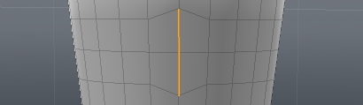
Note: Later, we'll use Modo to round the hexagon into a smooth oval.
To Shape The Attachment Edges:
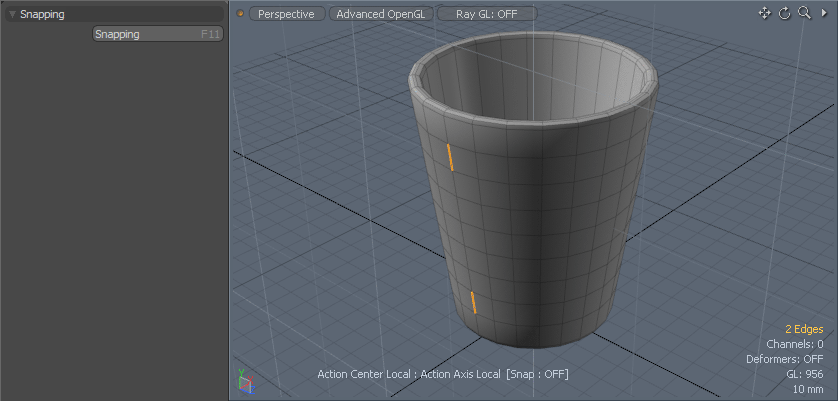
| 1. | Set the selection mode to Edges. |
| 2. | Rotate the view to see the left side of the mug body looking down the x-axis. |
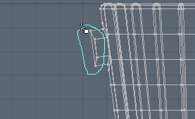
| 3. | Select the two edges one span away from both the top and bottom of the mug, that are aligned to the XY plane, as shown in the image below. |
| 4. | To the right of the modes toolbar is the Action Center selector button. Click on it to open the dropdown menu and select Local. |
| 5. | Press R to activate the Scale tool. |
| 6. | Scale only the Y (green) axis to 180% by clicking on the green handle and dragging it upward. |
Both edges scale.
| 7. | Drop the scale tool. |
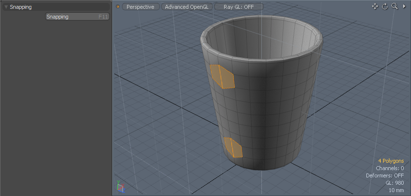
To Extend the Connection Buds:
| 1. | In Polygons mode, select each polygon at either side of the edges you just scaled (see below). |
Four polygons should now be selected.
| 2. | Activate the Polygon Bevel tool by pressing Shift+B and then clicking in the 3D viewport. |
Note: The Polygon Bevel tool handles may not appear in the correct location, but they still work correctly.
| 3. | Adjust the Inset (red) handle to 3 mm. |
| 4. | Hold Shift and click somewhere in the viewport to reset the Bevel tool, then bevel outward (with the blue arrow) to a Shift of 5 mm and drop the tool. |
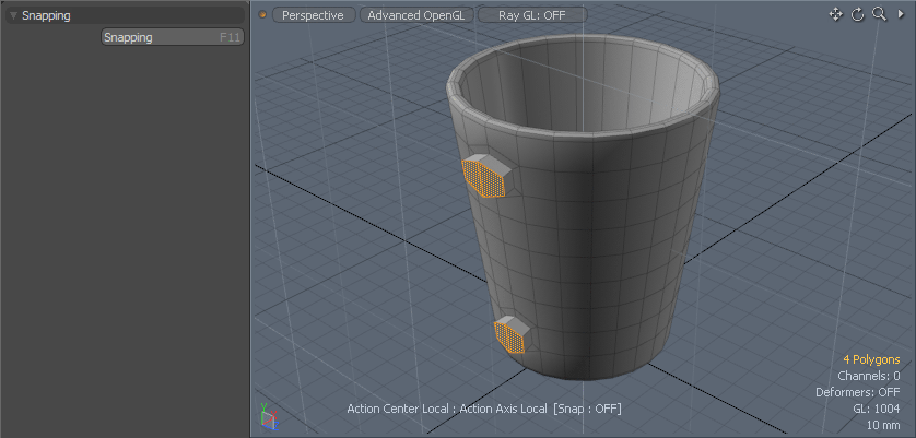
Adjusting Bud Size
The height of each bud is a little too tall, so let's scale them down.
Tip: To speed up the selection, Modo offers some shortcuts. By holding Shift and pressing the Up arrow, you can extend the selection to include the neighboring polygons.
To Select Neighboring Polygons and Resize:
| 1. | With the 4 polygons still selected, press Shift + Up. |
The selection is extended to all adjoining polygons and both buds are selected.
| 2. | Press R to activate the Scale tool and scale the height of the handle buds to 75% on the Y (green) axis. |
Note: Local Action Center is still active from the earlier procedure, so you can scale each one independently with the one action.
Introducing Orthographic Views
So far we've been working in the Perspective view, which shows a 3D view of the object and allows us to explore the space in all axes by 360 degrees. This view is great for most of our needs, but sometimes it's easier to switch to one of the Orthographic views to do some detail work. Orthographic simply means that we view the object looking from one side, and see it in two dimensions.
There are several orthographic views in Modo, including Top, Front and Right. Working in an orthographic view is ideal if you want to focus on a specific side, or limit transforms to two dimensions. You can see the default orthographic views in a four-view layout by clicking on the double arrow  icon in the top-right corner of the perspective view .
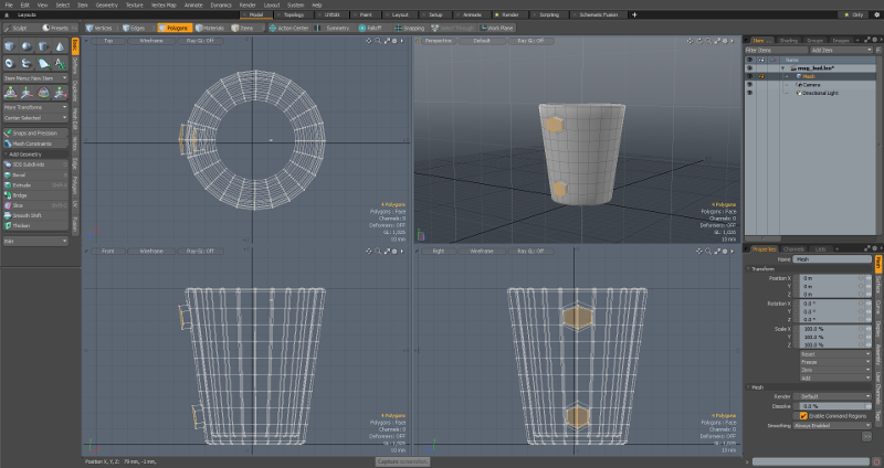
The window on the top-right shows the perspective view. By default, the orthogonal views are drawn in Wireframe mode. Wireframe mode shows objects as wire meshes, drawn using only vertices and edges. You can see the type of view and the draw mode in the top-left of each window.
Centering the Model
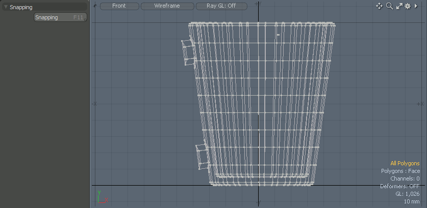
The next steps rely on the buds being aligned with the X-axis, such that if you look from the Top view, the buds extend to the left with the X-axis at their center, as shown below.
To Rotate the Top View:
| 1. | In Polygons mode, deselect all polygons. |
| 2. | Click the multi-viewport button to open the four-view layout. |
| 3. | Set the Action Center to Origin. |
This puts the center of rotation at the world origin (X=0, Y=0, Z=0).
| 4. | Press E to activate the rotate tool. |
| 5. | In the Top view, click and drag to align the buds with the X-axis (as above). |
| 6. | Press the spacebar to drop the Rotate tool. |
Introducing Lasso Selection
The lasso selection method lets you select regions of an object by drawing a boundary around the region. To use the lasso, press and hold the right or middle mouse button and drag the selection lasso.
Note: A polygon is only included in the selection if the entire polygon is within the lasso boundary.
|
|
|
| An orthogonal view. The mug handle has been selected using a right-mouse lasso selection. | The result of the lasso selection as seen in the orthogonal view. | The selection as seen in the perspective view. Note how the selection includes both sides of the handle. |
Note: You can use either the right-mouse or middle-mouse when drawing a lasso with different results. In Wireframe view, right-mouse + drag selects elements at the front and any that are occluded, middle-mouse + drag selects only elements in front.
In a non-wireframe draw mode, such as Default, the reverse applies.
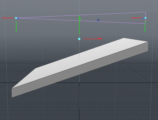
Connecting the Handle Buds
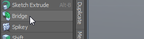
The next step is to connect the two buds using the Bridge tool. This tool creates new tube geometry that connects two selected areas. To help Modo make a good bridge, the connection surfaces must be slightly inclined towards each other.
Note: You can use the Bridge tool with polygons or edges.
To Orient to Bridge:
| 1. | Drop any active tools and deselect any polygons. |
| 2. | If you haven't already, click the multi-viewport button to open the four-view layout. |
Tip: Click in a viewport and press A to fit the object to the viewport.
| 3. | Set the Action Center type to (none), to use the default action center. |
| 4. | Locate the orthographic view of the upright mug with the handle buds extending out to the side. |
| 5. | Right-click+drag around the polygons on the outside surface of the top handle bud. |
Tip: Remember, a polygon must be completely within the lasso to be selected.
Tip: Adjust the Perspective view so that you can see the buds and make sure the selections are correct.
| 6. | With the two polygons now selected, press E to activate the Rotate tool. |
| 7. | Use the rotation handle to rotate the polygons downward 20 degrees. |
Tip: The Offset Angle is shown at the bottom of the Modo window, below the viewport.
| 8. | Drop the Rotate tool. |
| 9. | Repeat steps 3 to 7 with the lower handle bud, but rotate the lower bud upward 20 degrees. |
To Apply the Bridge Tool:
| 1. | Press the spacebar to drop any active tools. |
| 2. | Select the outward faces of the handle buds on both the upper and lower bud. Hold Shift when selecting to add to an existing selection. |
| 3. | Activate the Bridge tool from the Polygon sub-tab of the toolbox. |
| 4. | Click in the Perspective viewport to enter interactive mode. |
A single set of polygons is drawn as a straight line between the groups.
| 5. | In the Properties panel, set the Segments value to 10 to add polygons to the bridge. |
| 6. | Adjust the Tension value to 200%, curving the handle out. |

| 7. | Drop the tool. |
Creating Falloffs
Instead of moving the geometry as a single rigid piece, the falloff lets you move one area more than another, with a soft fade between the two extremes. This lets you apply bulges or slopes to a surface easily.
A falloff is often drawn as a wireframe in the viewport (depending on the type), with editing handles to change the shape of the falloff and adjust its intensity.
You can add falloffs to a tool separately, or, in the case of some tools (including the Soft Move tool), a falloff is added automatically to give the tool its characteristic behavior. In both cases, the falloff and the transform are shown as two separate tools in the viewport.
There are several types of falloff, each describing a different shape for the falloff region. For example, a Linear falloff is drawn as a wedge shape, where the geometry closer to the narrow end of the wedge is affected less than the geometry at the wide end. The amount of the affect has a gradual, linear change along the length of the falloff.
The images below compare the effect of a vertical (Y-axis) translate with and without a Linear falloff.
|
|
||
| The object is translated in the Y-axis, without a falloff. | |||
|
|||
| The object is translated in the Y-axis using a linear falloff. You can see the falloff above the object. |
The Soft Move tool uses a spherical falloff. The geometry at the center of the sphere is affected the most, and the effect softens to zero at the edge of the sphere. This lets us move the geometry with minimal changes at the edges of the drag region.
Shaping the Handle
We've made the geometry for the handle, but it doesn't match the shape in the original photo. To fix this, Modo has a palette of tools to deform shapes and bend geometry.
In this case, we'll use the Soft Move tool. The Soft Move tool lets us drag geometry in any direction. This is similar to the regular translate tool (W key) but the Soft Move tool uses a falloff.
To Soft Move the Handle:
| 1. | Return to single view perspective mode by clicking the double arrow |
| 2. | Drop any active tools. |
| 3. | Orient the viewport so that you are looking at the side of the mug with the handle extending to the left. |
The Work Plane snaps to the facing plane.
| 4. | Select the entire handle (front and back) using middle-mouse and drag. |
You'll have to move the viewport to select missed polygons or deselect unwanted polygons.
Tip: Remember to add to a selection using Shift + click and to remove using Ctrl/Cmd + click.
| 5. | Under the Deform sub-tab of the toolbox select the Soft Move tool. |
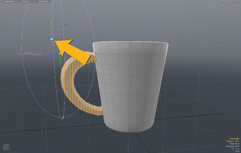
| 6. | With the mug facing you and the handle to the left, click above the left edge of the mug handle, level with the top of the handle, to position the tool as shown below. |
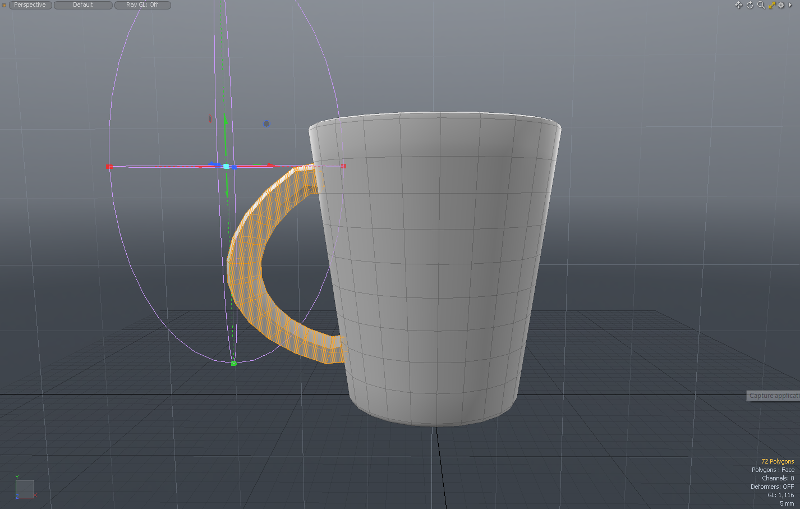
The tool has two components, the falloff and the move control. At first they are in the same position.
| 7. | Resize the width of the falloff so that it only covers the handle. Drag the red (X) box at the edge of the falloff to the left, up to the edge of the handle. |
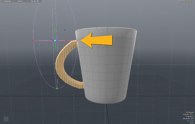
| 8. | Rotate the viewport to see more of the mug handle. |
| 9. | Use the blue box, at the intersection of the pink lines, to widen the falloff, so that it resembles the one below. |
Tip: When dragging the blue box, be careful not to select the blue arrow that drags the move tool. if you drag the move tool the mug handle moves. If this happens, Ctrl + Z and try again.
| 10. | Orient the viewport to look at the side of the mug with the handle to the left (see below). |
The work plane will align to the handle.
| 11. | Click and drag the upward green arrow to lift the move control. |
Now the falloff control and the move control are in different positions and can be controlled separately.
| 12. | Try dragging the move control up and to the left to raise the top of the mug handle. |
Tip: If you use the light blue box at the center of the Move control, the Move control shifts in the Work Plane, as does the handle geometry.
| 13. | By careful adjustment of with move tool and the falloff, you should be able to reshape the handle to look roughly similar to the original (it doesn't have to be perfect!). |
| 14. | When you're happy with the handle, press the spacebar to drop the tool. |
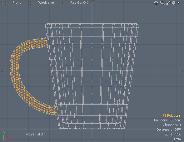
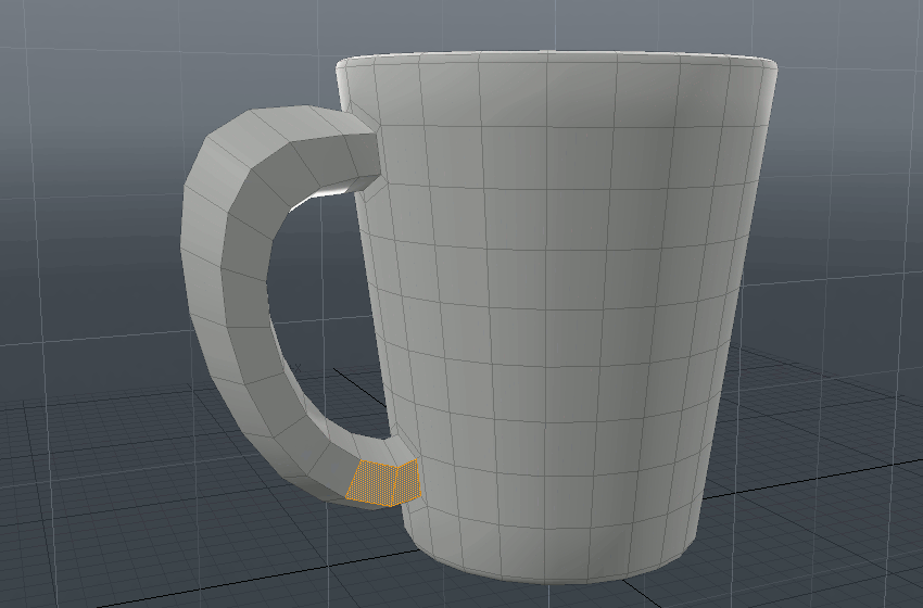
Evening-Out the Handle
In our model, the top of the handle is wider than the top, but in the original mug, the handle is an even width along its length. This can be fixed with the Rotate tool. We just need to rotate each side of the handle slightly to straighten them up.
Tip: To quickly select elements in a strip, select the first two elements and then keep pressing Up to select the rest.
To Rotate the Sides:
| 1. | With the side of the handle facing you, paint-select the first two polygons at the base of the handle. |
| 2. | Press Up a few times to select the entire side. |
| 3. | Rotate the viewport so that the handle is at the center of the mug. |
| 4. | Activate the Rotate tool (E key) and adjust the facing rotate circle until the side of the handle is straight. |
| 5. | Drop the Rotate tool. |
| 6. | Repeat steps 1-5 for the other side of the handle. |
| 7. | Press Esc to drop the selection. |
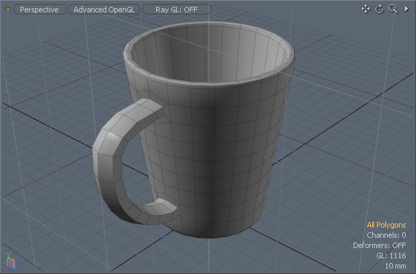
Smoothing the Surface and Adding Color
Although similar in shape to the original, the model of the mug is made of flat polygons and has a blocky appearance. To fix this, we can apply subdivision surface smoothing to automatically add detail to the mug and give it a smooth, rounded appearance.
Finally, we'll give the mug a color similar to the one in the photo. In Modo, color and other surface details of an object are stored in a Material.
To Subdivide and Add Color:
| 1. | Deselect any polygons by clicking away from the mug in the viewport. |
| 2. | Subdivide the model by pressing Tab or select Geometry > Toggle Subdivision. |
This adds additional polygons to the model that are formed from the base low-resolution mesh.
| 3. | Press M to open the Polygon Set Material dialog. |
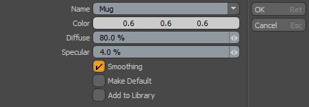
| 4. | Call the material 'Mug'. |
| 5. | Click on the color values to open the color picker. |
| 6. | Set the Red, Green and Blue values to 45. Click OK. |
| 7. | Save your model. |
Next Steps
Well done, you've successfully made a 3D model from scratch!
To see your mug using a more sophisticated rendering mechanism, change the drawing method from Default to Advanced, using the center button in the top-left of the viewport.
The next step is the Render the Mug. Here, we'll set up a simple scene with a collection of mugs, add the logo, and render out our scene into a finished image.