The Cut, Copy, and Paste commands work together to provide you with the means to easily move UV values around between different surfaces. UV editing uses specific Cut, Copy, Paste, and Delete commands found in a menu in the default UV layout toolbox, under the Edit UVs button. Click and hold to open the pop-up with all the command options or right-click to open immediately. All commands work on the currently-selected UV map. Maps can be selected either on the Mesh Item's Properties panel, or under the UVs section of the Lists viewport.
![]()
The Cut UVs command transfers the UV values for the selected geometry to the internal buffer and then removes the values from the selected geometry. Once values have been stored, they can be applied to a future selection, using the Paste UV positions command.
The Copy UVs command clones the UV values for the selected geometry into the internal buffer. Once values have been stored, they can be applied to a future selection using the Paste UV positions command.
The Paste UV positions command applies the UV values stored in the internal buffer to a target selection of geometry. When invoking the Paste UV positions command, a dialog box opens, offering you the ability to choose from two different Modes: Connectivity, which pastes the UV values, based on topological connectivity, and Selection, which pastes UV positions.
The Connectivity mode allows you to copy UVs from one surface to another with same topology, without worrying about selection order. The second option, Selection, pastes UV positions in the buffer to the target polygons, based on their order of selection.
The Transfer UV positions command is used to easily transfer UV mapping values between identical topology, eliminating the two step copy and paste process. The transfer process can be applied to multiple surfaces at the same time and is done by way of selecting polygons in a specific order. This is done by selecting two adjoining polygons on the UV source surface, then selecting the exact same two polygons on the target surface in the same order. For multiple targets, continue making the same selections on each subsequent surface. Then, by invoking the Transfer UV positions command, the UVs transfer from the source UVs to all the targets at once.
NOTE: Targets need to have the same topology, meaning the geometry and point count must be identical, but transform, scaling, and deformations can be applied to any of the targets without affecting the transfer results.
The Delete UVs command removes the UV values from the selected geometry for the selected UV map.
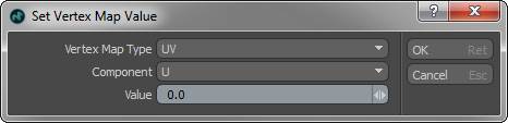
The Set Value dialog allows you to define a specific UV value for a selection of vertices. This is useful, for example, to force a selection of vertices against a specific UV section edge for instance. To use, select the target vertices and then invoke the command Set Value from the menu. In the dialog, the Vertex Map Type defaults to the UV option. You can then define the component the value is attributed to - the U (horizontal direction) or V (vertical direction). Then the Value input files define the specific UV position along the grid. Press OK to assign the value to the target, moving them to the defined location.